
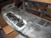
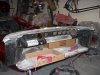
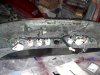
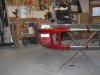
It has been a while since I have posted any updates. I have been working on the dash some. I fabricated the switch panels, cut out the gauge openings, and change the demister vent opening to fit a '65 Mustang Vent. Here are some pictures of the dash:

You are using an out of date browser. It may not display this or other websites correctly.
You should upgrade or use an alternative browser.
You should upgrade or use an alternative browser.
Jonathans RCR 40 Build
- Thread starter jonathans
- Start date
Jonathan;
Looks like you are moving along. I have a question about the 65 Mustang dash vent....It looks larger than original in your photos, and if its not too much trouble could you post some measurements, also what is the availabilty of that item. I haven't looked yet, but I know there are a lot of parts available for Mustangs in the aftermarket, or maybe this one might have to be sourced at the boneyard?
Thanks
Phil
The Mustang vent is a little narrower than the original. The length is shorter than the length of the longest side of the original but about an inch longer than the shorter side, if that makes sense. I will post measurements later. On availability they seem pretty common on ebay. Search for
"Mustang speaker" and you should find one. From what I hear a 63 Comet vent is a better fit but they are harder to find.
"Mustang speaker" and you should find one. From what I hear a 63 Comet vent is a better fit but they are harder to find.
Hi Jonathan,
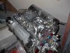
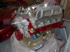
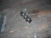
Looking great, nice work. Re your engine & the coolant system vent lines you ran from the back of the manifold to the thermostat housing.
How did you drill & tap the inlet manifold & do you have any picture or advice?
I've been thinking about doing the same & would appreciate any tips!
Regds,
Looking great, nice work. Re your engine & the coolant system vent lines you ran from the back of the manifold to the thermostat housing.
How did you drill & tap the inlet manifold & do you have any picture or advice?
I've been thinking about doing the same & would appreciate any tips!
Regds,
I taped it with a 1/8 NPT. I think that 11/32 was the closest bit that I had. I believe that an R or S is what is correct but I do not have any lettered bits. I just used the gasket to locate it so that it lined up with the coolant passage.
The vent lines are supposed to make burping the engine easier. Hopefully they will help.
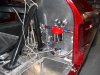
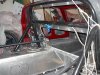
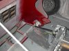
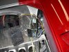
I have started wiring the car. I have been using weather packs for all the connections under the front or rear bonnet. I have been using molex connectors under the dash. I have done all the wiring for the lights and the dash gauges and indicators. I still have the switch pannels to do and the engine compartment. Here are some photos:
Attachments
Howard Jones
Supporter
Joathan, I had a fairly big problem with cooling and getting the air out of my system and I solved it as follows.
The bleed lines you have put on the water passages at the rear of the motor are correct. BUT I ran mine to the temp sensor bung at the front top of the intake. This is the highest point in the water system internal to the engine. Then I ran another line from a Y on the temp sensor bung to the side of the header tank at a point about 3/4 of the way to the top. I welded a bung on the thermostat housing to accommodate the temp sensor where the bypass line would go if I had a thermostat. Without one its not needed.
This arrangement will allow any air inside the motor to bleed back to the header tank. This is where you want some air. Nowhere else. I am afraid that your arrangement will only purge the rear of the engine but leave the air in the rest of the system. I think you can fix your system without much drama buy running the right rear bleed line over to the left rear port and then T it there and run them both to the existing port on the thermostat housing. Then run the other longer line from the the other port on the T housing to the headertank. Nearly the same arrangement.
I also ran a bleed line from the radiator back to the same port on the side of the header tank. My radiator has side tanks as do most GT40 radiators so it was necessary to braze a bung on the top of each tank and Y them together so that a line could be run back to the previously mentioned header tank. Thsi assures that any air that reaches the radiator is purged back to the header tank, keeping the air out and the radiator full of coolant.
This bleed system will purge the coolant system so well that all I do when refilling the system is pour coolant into the fill cap hole. You can hear the system purging itself as it fills. I have never had a problem with air in the system since.
I should also add that I do not have a heater core in my car. I believe this can be a place where air can be trapped also. If I did have a heater core in my car I would run a bleed from it back to the header tank also.
Lastly I have removed my thermostat and run the car with a restrictor (disk with a hole in it) in its place . I have a otherwise stock GTD radiator with the return line moved to the bottom. They are not known for being the most efficient radiator but with all the air out of the system they can be made to work well enough.
I have driven my car on a 110F day for 3 hours on a long freeway trip and the water temp never went over 205-208F.
Good luck, Your car looks great!
Last edited:
Does this just remove air from the rear of the heads or does coolant flow also help to releave a hot spot? If it is just for air removal and you dont want to run all the lines you can just tap the holes in the intake and put bleeders. When you fill the coolant system you then crack these bleeders open to remove air. You will want to do it after running to get any other accumulated air out that may collect there. I did this on my off road buggy and it worked great. It requires a little more effort when you change coolant but eliminates lines.
.02
Jim
.02
Jim
Howard Jones
Supporter
The problem as I see it is the long coolant lines and the overall complexity of a coolant system in a GT40. Even without the heater you have a lot of length in the pipes AND the radiator is lower in the system than the engine. Since the air will accumulate in the high spots like the top of the radiator tanks and at the rear of the heads, you must purge it or the radiator will get effectually smaller and smaller in area as it fills with air. The heads are even a bigger problem because you will get hot spots and all kind of tuning problems will result not to mention the potential damage of engine dammage.
Added to this is running the engine at high RPMS and causing cavitation in the water pump. This last problem can be partially corrected by running the pump slower with a larger pulley on the pump but air still does develop in the system if the car is run hard as at a track event. If you run the pump too slow then you will have cooling issues on the street at low engine speeds. Its better to get the air out as it developes.
Adding a constant bleed system will continuously purge the coolant system of air as the motor is run. Mine took a lot of time, some money, and experimentation to get it to work right but now all my heating problems are solved. This is in a car without a expensive high tech aluminum radiator and about 350-375HP.
The manual bleed valves will work but only when you pull over and use them. This can be a issue at a track day event or a long hot stop and go freeway run. I find overheating cars to be such a pain in the ass that I will go to just about any lengths to solve these types of problems.
The only problem I have now is the car runs too COLD when it is run in air temps less than about 60F. I will need to experiment with different flow restrictor disk hole sizes or block off part of the radiator in the winter.
I believe the original GT40 race cars used a system much like mine.
Last edited:
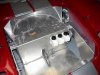
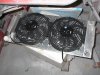
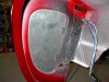
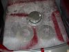
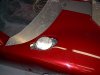
I also did some tin work. I made a fan shroud, block off plates for the headlight cavities, shims for the gas caps, and a license plate bracket. Here are some pictures:
Attachments
Similar threads
- Replies
- 25
- Views
- 3K
- Replies
- 18
- Views
- 3K