Primary pipe length formula

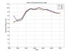
The formula for primary pipe length of 4 into 2 ito 1 exhaust header is:

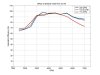
P = 850 X ED divided by rpm -3

Where rpm is the engine speed the exhaust is being tuned to & ED is 180 deg plus the number of deg the exhaust valve opens before BDC.

Does this stand true when compared to a crossover system as used on a GT40?
If so, then the ideal pipe length is around 27", but this conflicts with the common accepted length of 36". Can anyone shed some light on this?
 
The “Bundle of Snakes” exhaust is not a 4 into 2 into 1 system. It is a 4 into 1 system taking advantage of the scavenging effect of connecting cylinders with equal pulse spacing in the same collector.

The equation for a 4 – 2 – 1 system would not have any applicability to what is used on the GT40.

If you have the equation for a 4 into 1 system it would be interesting to compare that, although using the equally spaced pulse type system has large enough advantages that you are probably ahead of the game by using pipes a couple of inches longer than optimum if you need to do that to get them to reach.
 
There is no simple formula. I have seen several that are quite different from one and other. There are just too many variables involved for a simple formula to work.

There is no doubt, gas flow modeling software that is used by the Formula 1 teams, NASCAR, etc. It would be way too complex to ever reduce to a simple rule of thumb.

The best I can suggest is to look at various header manufacturers websites (Hooker for example: http://www.holley.com/HiOctn/ProdLine/Products/ES/ESHHSCH/Car.html ) and get a general idea of what has proven successful. Look at smallblock headers for Ford and Chevy. You can get a rough idea of the RPM range they were optimized for by looking at the primary tube OD.

I know this isn’t what you want. A nice simple formula would be wonderful, but I have never seen one that was really accurate.

If it helps, Primary tube diameter is probably more important than length, and there is a formula for that:

Cross Sectional Area of a Port or Exhaust Manifold:

Area = Volume of One Cylinder x Peak Torque RPM / 88200 (You then convert Sq. In. to dia.)

The Header inner diameter is the OD minus 2 x the wall thickness which is 18 ga. = .051” - 16 ga. = .063”

This works out to: 1 5/8” = 1.52” 1 3/4" = 1.65” 1 7/8” = 1.77” 2” = 1.90” 2 1/8” = 2.02”
 

Brian Kissel

Staff member
Admin
Lifetime Supporter
If you are looking for "GOOD" information on headers, try this site. Headers by Ed Take the time to read all that is there, and also note, that there is a 90 minute audio tape available that discuss's header design. Be sure to read the part "Ramblings". I think you will like it.
Regards, Brian
 
Cheers Guys,
Some good info on these sights. Infact the products they sell are, as ever, considerably cheaper than hre in the UK. Might be worth considering buying from the US. Hmmmm!!!
 

Adam C.

GT40s Sponsor
Since I have access to one of these simulation codes, and have some experience in the area, I thought I would use this as an opportunity to do a little exhaust study.

The following graphs were made using a 1-D time-domain simulation code. This is NOT anything like desktop dyno.

The engine used was a 5.0L EFI engine with the following spec's

Ported GT40X heads flowing 240 CFM intake and 230 CFM exhaust at 28 in H20.
10.3:1 compression
X303 camshaft (224 @.050", 112 LCA)
ported Explorer intake manifold with runners shortened 1.5"

Although an EFI, it is similar to many of the engines in GT replicas.

The common dimensions for the exhaust system are as follows:
36" long primaries with ID of 1 5/8"
36" long secondaries with ID of 2" at the collector and 4" at the outlet.
180 degree pulse-separated firing order
no crossover conecting secondaries.

These dimensions are somewhat representative of those used in the originals. Each of these parameters will be manipulated one at a time to study their effects. All parameters in the following graphs will be as listed above unless noted.

All of the runners were simulated as being perfectly straight and exactly equal in length. The only effect due to bends is increased flow losses, provided the centerline lengths are equal.

In all of the following plots we are comparing engine volumetric efficiency. This quanity is free from additional error sources like mechanical fricition estimation. Fpr those that must think in torque in and HP, the % difference in Volumetric efficiency is roughly equivalent to that in Torque.

First we look at primary runner length by simulating primary runner lengths of 24, 36, and 48" (see attached file). This should easily cover all the possible lengths that can occupy a GT engine bay.

Interestingly, the longest primary simulated provides the best results over the useable range of this engine.
 

Attachments

  • 27285-primary length.jpg
    27285-primary length.jpg
    93.3 KB · Views: 1,936

Adam C.

GT40s Sponsor
Now we look at secondary runner lenght effects.

The effect here is much less than that of primary runner length. The results are also somewhat mixed. In general, longer secondaries seem tgo be better at low RPM, while shorter may be better at high.
 

Attachments

  • 27286-secondary length.jpg
    27286-secondary length.jpg
    92.5 KB · Views: 1,547

Adam C.

GT40s Sponsor
Next up is primary runner diameter.

Again, not much here.
 

Attachments

  • 27288-primary diameter.jpg
    27288-primary diameter.jpg
    88.9 KB · Views: 1,396

Adam C.

GT40s Sponsor
It is often said that merge collectors and tapered secondaries make more power. Here we compare the tapered secondary that starts at 2" and increases to 4", with a straight secondary that is 4" allong the entire length.

Here the straight duct wins. It should be noted that the code does not take into account the difference in flow losses between the tapered and striaght ducts.
 

Attachments

  • 27289-secondary taper.jpg
    27289-secondary taper.jpg
    90.6 KB · Views: 1,410

Adam C.

GT40s Sponsor
Finally the mother of all. The effect of pulse separation. On this plot is the GT style 180 deg. exhaust compared to the bank-to-bank system like that used on the lowly Mustang.

The equal pulse system performs slightly better at high RPM, while the bank to bank system is better at low.

It should be noted that these are cylinder averaged vol eff curves, and that the cylinder to cylinder balance on the equal pulse system is far superior to that of the bank to bank.

The equal pulse system also has that great tone.
 

Attachments

  • 27291-pulse.jpg
    27291-pulse.jpg
    90.6 KB · Views: 1,433

Adam C.

GT40s Sponsor
People often talk about the importance of equal primary runner length. Although not simulated here, I have done it in the past and can tell you the effect.

Differing the primary runner length effectively broadens and smooths the torque curve. Consider the first plot with varying primary runner length. Generaly speeking, if half of the runners were 24" long while the other half was 48", the overal engine vol. eff. would be something between these curves.

It is important to remember that these results apply to this engine and headers that have comparitive lengths and diameters to those simulated here. They should not be used to predict the behavior of a 426 Hemi in a front engine drag car with bank to bank exhaust and 2.25" primaries.
 
Adam,

Thank you for the information!

I have known you were out there from some of your other posts and was hoping you would jump in on this one.

I have one question if you have the time to run one more simulation. (I would love to have a copy of your software.)

What happens if you use a flat (180 deg.) crankshaft with normal headers? Does it equal the graph for the Bundle of Snakes on a conventional 90 deg. crank engine?

I was surprised by the graph of Primary Tube size. I would have expected the large pipes to have moved the torque peak up noticeably on that small an engine. Also the VE was very good – 95% up to 5,500 RPMs with those Heads (Is the exhaust flow really that high compared to the intake flow? That seems like a very high number for the exhaust.)

Thanks Again,

Kevin
 

Adam C.

GT40s Sponsor
Kevin

I believe that a 180 crank has a firing order that alternates from bank to bank. If this is true then all of the cylinders on one bank would be separated by 180 deg., and so would be grouped together for an equal pulse system.

All you have to do is look at the firing order. You could even change the cam and firing order in a 90 deg crank and get the same effect. I believe it is not done this way for dynamic reasons.

Becuase of the comparatively low RPM operation of these engines, the intake system still dominates in tuning. Only after the intake runners are really short (~10,000 RPM) does the exhaust start to be really important.

Adam
 
Wow, Adam, nice job. I just love a thread like this one that's just dripping with tech.

I'm curious as to what the comparative VE would be for an engine that doesn't have equal-length primaries, as well as what the difference would be in horsepower. How close in length do the primaries need to be to be considered "equal length?" I would think that, with the extra distance one primary from each side has to go to to serve as the crossover pipe, truly equal-length primaries may be difficult to achieve on a GT40.
 
By the way Adam,

If you ever want to do a thread on intakes, especially the difference between Webbers on an IR manifold, a 4-barrel carb on a high-rise dual plane, effects of changing intake port size, etc. I for one would find it fascinating.

I don’t want to take a lot of your time up on this, but you have access to information a lot of us would really like to know but have no source for.

Have you considered writing a book? There are a lot of gearheads out there that would probably pay a good bit of money for this kind of information.

Thanks Again,

Kevin
 
I purchased all the bends, tubing, collectors, etc for my system from Burns. Vince at Burns input all the data from my engine into their software to arrive at tubing sizes. The engine runs to 6K rpm.

Calculated values for my 351C with 2V heads.
Primary diameter was 1-3/4".
Secondary diameter was 3".
Primary length was 36 or 37" if I remember correctly.

Actual values as fit to the car were
Primary diameter 1-3/4"
Primary length 38"
Secondary diameter 2-1/2"

The primary length is pretty much dictated by head design and room around the engine. There isn't much room to vary anything with the C engine and ERA's tub/bodywork.

Secondary diameter was reduced to quiet the exhaust for street use. The collector merge angle was increased over what Burns normally uses to make the collectors shorter and allow as much room for mufflers as possible. I fitted Edelbrock RPM series SS mufflers. The car is reasonably quiet, but with a nice deep growl.

My system "is" equal length on all 8 pipes...within 1/2" of each other anyway. #4 and #8 are the two most difficut to get the length of tubing required.
 

Adam C.

GT40s Sponsor
Mark,

As a fellow CC'er I know your thirst for tech. Just be carefull bringing any of that wicked bunch over here. /ubbthreads/images/graemlins/grin.gif

I told you what differing the primary runner lengths would do in general, but lets look at a specific case.

According to Dave, the two rear cylinders are the hardest to get equal length. I would assume that they would end up short since they are closest to the collectors.

So using our trusty 5.0L with our original GT exhaust, I shortened these two primaries in 2" increments from 36" to 30".

As you can see there is little difference. As I predicted, making the lengths uneven tends to smooth out the VE, and therefore torque curve.

On the exhaust side, the cylinders don't really work together. Each one is singing its own song. It is not important that they all be singing exactly together. Of course it will sound better if they are. Also, the cylinder to cylinder variation will be less in an equal-length design. For unequal length, the VE curve is different for each cylinder. As a consequense, if you are injecting the same amount of fuel for each cylinder (as in most port injection systems) some cylinders will be rich, while others will be lean. In the model here, we are assuming that each cylinder gets a stoich mixture.
 

Attachments

  • 27358-unequal.jpg
    27358-unequal.jpg
    92.4 KB · Views: 1,312

Adam C.

GT40s Sponsor
Kevin,

I don't think I am the one to write a book. There are many people out there (probably learking on this forum) that know far more than I.

If you are looking for a good read, I can suggest two:

1. Internal Combustion Engine Fundamentals by J.B. Heywood is a great overview of all the major aspects of ICE's.

2. Design Techniques for Engine Manifolds, Wave Action Methods for IC Engines by Winterbone and Pearson is great for those that want to learn about resonance tuning.

Non Engineers will have a tough time reading these (particulalrly the second one) but they aren't too far out there.

As for the VE of the engine. It is not all that supprising that it is approaching 100% VE. Now when it goes over 100% you really know you are doing your job. Typically, I think higher VE's are possible at higher speeds.

The exhaust flow of these heads was a little out there. I ported the heads a few years ago. I simply cleaned up the bowl on the intake side and had a good valve job done. The peak flow number hardly changed for the intake, but at mid lift it actually well outperformed the TFS TW.

I ported the crap out of the exhaust, hence the high numbers. They were flowed by Fox Lake before I had access to a flow bench (I now have access to one of the best). The superflow bench that is the gold standard in the hotrod industry doesn't do so well measuring flow out of the cylinder. The measured flow of 230 CFM actually is theoretically impossible for a 1.54" exhaust valve, so the numbers are deffinitely botched.

So why did I use the exhaust flow numbers then? Because at that range, the exhaust flow has little to do with VE. You can never have too much exhaust flow, but you can have too little.

In this plot we look at the effect of varying the exhaust valve flow. Beginning with our initial maximum flow of 230CFM, I decreased the flow ability of the exhaust valve in 25% increments until it really began to hurt VE.

VE doesn't really start to take a hit untill the exhaust is flowing about like the stock E7TE head (115 CFM). There is a small penalty at low RPM for using the high flowing head. This is primarily because it is easier for the exhaust gases to back flow during valve overlap. This could be remidied by using a cam that had less overlap, but then power up top would suffer.

Maybe if you all like this, I can set aside some time to do an induction expose'.
 

Attachments

  • 27359-exhaust.jpg
    27359-exhaust.jpg
    94.6 KB · Views: 1,349
Back
Top