SLC 24 Howard Jones

Howard Jones

Supporter
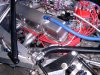
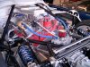
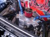
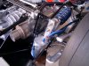
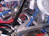
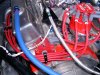
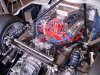
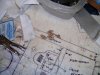
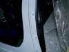
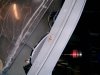
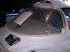
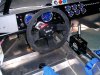
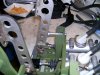
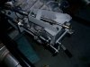
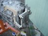
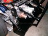
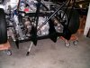
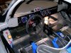
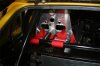
So as I was doing the throttle cable I realized that The original peddle set that cam with the car was ...........well less than optimum. What to do buy a wildwood set, or a Tilton..........NAAAAAAA! Fix it!

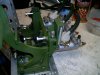
So here what I thought I needed to do.

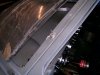
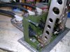
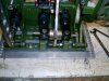
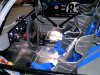
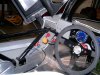
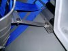
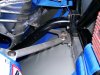
1. clutch peddle needs a stop.
2. throttle peddle needs a travel stop
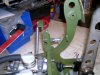
3. add spring to throttle peddle for track inspection purposes (more on that latter)
4. add throttle position adjustment so that it can be set to same rest position plane as brake peddle
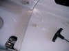
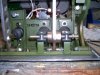
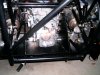
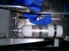
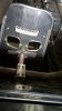
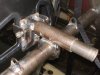
5. cut all three master push rods to proper length
6. add jam nuts to push rods (had to add threads to rods)

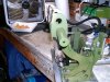
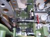
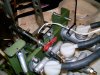
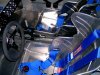
More on 3, I have been hearing that more and more tech people are looking for two separate spring systems, not just two springs for throttle return, so I added another at the peddle end. See........two sets sir!

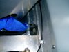
I also added a few more stiches of weld here and there. It all looks better now and I am more comfortable with the system having really spent a full day working on it. We'll see how it works latter when I get the car going. Maybe I saved a little money. I see why Fran puts a Tilton set in the car now however. I wouldn't send a Tilton peddle set back............hint hint.
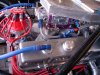
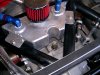
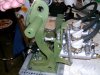
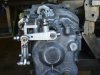
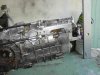
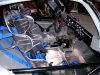
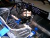
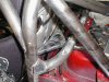
 

Attachments

  • HPIM1996.jpg
    HPIM1996.jpg
    187.3 KB · Views: 345
  • HPIM1997.jpg
    HPIM1997.jpg
    171.6 KB · Views: 282
  • HPIM1998.jpg
    HPIM1998.jpg
    173.3 KB · Views: 289
  • HPIM1999.jpg
    HPIM1999.jpg
    214.1 KB · Views: 290
  • HPIM2000.jpg
    HPIM2000.jpg
    170.5 KB · Views: 309
  • HPIM2001.jpg
    HPIM2001.jpg
    137.4 KB · Views: 269

Howard Jones

Supporter
Couple of more additions to the peddles. First was two small stages to keep the balance clevis's from drooping to one side or the other. I saw a picture of a open wheel car that had made a similar mod and I liked the idea, so I did it.

Second was a mechanically actuated electrical brake light switch. Why you ask. If the pressure switch type fails at the track then you will be doing a complete rear circuit brake bleed in a hurry so that you can get out the next session. Must have brakes lights period!

I put a setup in my GTD just like this one, more or less, for that reason. Hasn't failed me yet and if it does it's a 10 min switch swap out to fix it. I like easy fast fixes.

This peddle set is OK I guess but really not worth buying. The Tilton set you guys now get is so much better there really isn't a comparison. I just might get one later if this one doesn't work to my satisfaction.
 

Attachments

  • HPIM2002.jpg
    HPIM2002.jpg
    140.4 KB · Views: 304
  • HPIM2003.jpg
    HPIM2003.jpg
    197.1 KB · Views: 260
  • HPIM2004.jpg
    HPIM2004.jpg
    185.2 KB · Views: 286
  • HPIM2005.jpg
    HPIM2005.jpg
    177.8 KB · Views: 300
Last edited:

Howard Jones

Supporter
I have been doing my shifter mechanism at the gearbox end over. The first couple of try's was before I had my tig machine and I did them at work with a gas torch. Not so good, functional maybe, but not really up to my standard.

While I contemplated the desire to for a redo I ran across some pictures of another setup on a flipped G50. I think this is a better looking way to do it and all the pieces are a lot tighter to the gearbox. I don't remember who's this is but thanks for the inspiration. The first three are the target the rest are mine. Lastly you can see I have had the saws all out again as the diffuser gets smaller and smaller.

Rob says it at least looks like it works now..............whatever. I added a little 1 inch Gurney across the top at the trailing edge to add some rigidity. The whole thing is stiffer now than when I first started hacking on it. Battleship built!!!!!
 

Attachments

  • attachment 22.jpg
    attachment 22.jpg
    40.6 KB · Views: 279
  • attachment444.jpg
    attachment444.jpg
    38.6 KB · Views: 254
  • attachment44444.jpg
    attachment44444.jpg
    45.5 KB · Views: 281
  • HPIM2015.jpg
    HPIM2015.jpg
    145.7 KB · Views: 251
  • HPIM2016.jpg
    HPIM2016.jpg
    168.4 KB · Views: 224
  • HPIM2017.jpg
    HPIM2017.jpg
    151.9 KB · Views: 239
  • HPIM2018.jpg
    HPIM2018.jpg
    163.5 KB · Views: 227
  • HPIM2019.jpg
    HPIM2019.jpg
    164 KB · Views: 238
  • HPIM2020.jpg
    HPIM2020.jpg
    194.2 KB · Views: 221
  • HPIM2021.jpg
    HPIM2021.jpg
    198.4 KB · Views: 257
  • HPIM2022.jpg
    HPIM2022.jpg
    209.7 KB · Views: 256
The USS Mighty Mo. We are going to enter the 25 hour with this ship and put 'em ALL in the wall. :helmet:
Not.
 

Howard Jones

Supporter
Pretty much finished interior. The only things left are to have seat covers altered to the 2.5 inch shorter seat headrest height, put in the roll cage padding, and add labels on the dash. I made all the belt mounts as I really wanted to adhere to the belt install specs. Everything is in double shear, G8 hardware, and 1/8 4140CM. I also added a big horizontal tab to the back of the seats so that I could brace them to the bulkhead. Frigging seats are not going anywhere.

I was able to use a 6 point for the drivers seat because I could get the mount points back to the rear corners where they should be, but the passenger seat is mounted right on the floor so I could only use a 5 point due to the inability to place a mount any farther back than right at the rear of the center 5 point belt port through the seat. In both cases they are right where the manufacture wants them.

Pretty happy with the whole deal. Everything feels right and is perfectly placed for me. The passenger seat is safe and out of my way. I am going to think a bit on what to do with the passengers hands. Maybe look at some rally cars.

Pretty Spartan with all the home made panels and dash but this what I was going for. Old school, safe, analog, simple, two seat track car.
 

Attachments

  • HPIM2023.jpg
    HPIM2023.jpg
    199.6 KB · Views: 353
  • HPIM2024.jpg
    HPIM2024.jpg
    184.6 KB · Views: 324
  • HPIM2026.jpg
    HPIM2026.jpg
    194.4 KB · Views: 308
  • HPIM2027.jpg
    HPIM2027.jpg
    206.1 KB · Views: 296
  • HPIM2028.jpg
    HPIM2028.jpg
    214 KB · Views: 275
  • HPIM2030.jpg
    HPIM2030.jpg
    188.7 KB · Views: 256
  • HPIM2031.jpg
    HPIM2031.jpg
    153.5 KB · Views: 310
  • HPIM2032.jpg
    HPIM2032.jpg
    163 KB · Views: 257
  • HPIM2034.jpg
    HPIM2034.jpg
    182.6 KB · Views: 269
  • HPIM2035.jpg
    HPIM2035.jpg
    171.2 KB · Views: 240
  • HPIM2036.jpg
    HPIM2036.jpg
    181.6 KB · Views: 294
  • HPIM2037.jpg
    HPIM2037.jpg
    199.3 KB · Views: 262

Dave Lindemann

Lifetime Supporter
Howard - Beautiful work as always. Being in the safety profession I have to ask - did you consult with Kirkey before welding the brace across the back of the seats?

Regards,
Dave L
 

Howard Jones

Supporter
Dave I asked a guy who welds for a living and he told be to stich weld them on. So even thought they are about 10 inch's long there is only five 1 inch stiches on each side. I let the piece cool as I went along so as not to over heat the material.

Steve, looked them and told me "pretty enough" and OK as far as not over heating them up too much. You know what Kirkley would say. "We can't warrantee anything you do to them or tell you how to do anything" or some such legal thing. They will sell you a very similar piece that you can bolt on that does the same thing.

The seat is welded together. If welding was bad then it wouldn't have been welded together in the first place. I'm confident in the seat and my welding and I would bet that if you tested to failure it wouldn't be any weaker. But then what do I know.

Thanks for the concern.
 

Dave Lindemann

Lifetime Supporter
Howard -

I'm not worried about the quality of the welds. I'm more concerned about the placement of a rigid structure at a person's shoulder position. In a collision severe forces can come into play. If the structure welded to the seat is stronger than the back of the seat - and the seat is not designed to have structure there - it could cause severe injury to the person sitting in the seat. I don't know of any sports car seat that has the back of the seat rigidly mounted to the body/chassis/roll cage. My only intention is to bring the concern to your attention and I will leave it at that.

Best regards,
Dave L

Dave I asked a guy who welds for a living and he told be to stich weld them on. So even thought they are about 10 inch's long there is only five 1 inch stiches on each side. I let the piece cool as I went along so as not to over heat the material.

Steve, looked them and told me "pretty enough" and OK as far as not over heating them up too much. You know what Kirkley would say. "We can't warrantee anything you do to them or tell you how to do anything" or some such legal thing. They will sell you a very similar piece that you can bolt on that does the same thing.

The seat is welded together. If welding was bad then it wouldn't have been welded together in the first place. I'm confident in the seat and my welding and I would bet that if you tested to failure it wouldn't be any weaker. But then what do I know.

Thanks for the concern.
 

Howard Jones

Supporter

Attachments

  • 11365d1104635352-seat-back-brace-seatbackbrace.jpg
    11365d1104635352-seat-back-brace-seatbackbrace.jpg
    15.5 KB · Views: 261
  • 2012-09-05-17-01-071.jpg
    2012-09-05-17-01-071.jpg
    72 KB · Views: 338
  • P1010010.jpg
    P1010010.jpg
    38.4 KB · Views: 251
  • seat_installed_rear.jpg
    seat_installed_rear.jpg
    51.9 KB · Views: 282
  • P1010030.jpg
    P1010030.jpg
    88.5 KB · Views: 273
Last edited:

Dave Lindemann

Lifetime Supporter
Interesting reading Howard - I wasn't aware that seat back braces were allowed or even required for racing - I'm obviously not a racer! That being said, from the SCCA article:

"If a back brace is installed, check to make sure it is safe."
- and -
"The best recommendation we can make to drivers is to suggest that they follow the instructions from the manufacture of their particular seat."

Which goes back to the original question I posed.

It will probably never be an issue. I just felt the need to mention something because the seat is such an integral part of the driver safety cell and when a modification is made that has not been vetted with the manufacturer it raises a red flag for me.

Take care,
Dave L
 

Howard Jones

Supporter
Dave
After reading a bit more on this subject I think I may make some modifications. Replacing the two (each) braces with a single flat place to prevent (spearing) is one. Something like this is what I'm thinking.

https://www.discoveryparts.com/auto...mount-bracket-for-4119-9119-series-seats.html

These kind of discussions are the real value of this forum. This isn't the first time I made changes because someone saw something I didn't. You made me think and that's the true mark of friendship.

Thanks buddy!!! Merry Christmas
 
Last edited:

Dave Lindemann

Lifetime Supporter
Howard - I'm glad you don't think I was just being an ass! I would really hate for you - or anyone else - to be injured.

Merry Christmas to you too!
Dave L

Dave
After reading a bit more on this subject I think I may make some modifications. Replacing the two (each) braces with a single flat place to prevent (spearing) is one. Something like this is what I'm thinking.

https://www.discoveryparts.com/auto...mount-bracket-for-4119-9119-series-seats.html

These kind of discussions are the real value of this forum. This isn't the first time I made changes because someone saw something I didn't. You made me think and that's the true mark of friendship.

Thanks buddy!!! Merry Christmas
 
Howard's on the gas! It's amazing what a little free time can do for a fella. I been collecting stuff for a project I owe him, I better step up the pace.

Dave..... it just might be me in that seat so, I forgive you for maybe looking like the south end of a north bound horse :)

Happy HoHo my friend
 

Howard Jones

Supporter
Cary, I once offered a ride to someone from this forum in my GT40. He came to the track I was going to next in Nevada from Montana! He got his ride and the smile was so big I though he was having a stroke. Great times! I am building this car because I really like to give rides. Should you ever show up where we can do that then climb aboard.

Watch this buildlog and send me a PM when the car begins to get to the track.
 

Howard Jones

Supporter
Engine room complete. I believe that the vent tank and over flow tank that I made and their associated hoses completes the plumbing on the car also. I also added a oil fill tube and screw on cap. So now I am getting close to main engine start.

I added some water and right away found a couple of loose fittings and a band clamp. No matter how many times I think I have a foolproof system for checking these things it never works with out a dynamic test. I filled the engine and GRBX with oil the other day and no leaks there yet.

Last week I set the preload on the hyd lifters, pre oiled the engine with a drill motor, made the plug wires and their loom separators, and setup the distributor advance curve.

Finding compression stroke on #1 isn't easy alone on this car because the only place you can get to the crank bolt to turn the engine over is from underneath. This prevents me from seeing what is going on top. So I came up with an idea that worked for me. I used an leak down test fitting in the plug whole for #1 and slipped a balloon over the other end of the tubing. Then dropped the tubing down under the car so that I could see it blow up on the compression stroke as I turned the crank over. Worked good enough to pick which crank dampener rotation was the right one.

In one of there pictures you can see the gearbox fill plug that I modified to add a AN6 fitting. If I do run a pump later I will use this port to apply oil to the ring gear. There is another at the rear of the box around 5th gear and I had the cases drilled and tapped to add a drain fitting at the bottom along with a temp sensor.
 

Attachments

  • HPIM2038.jpg
    HPIM2038.jpg
    198.9 KB · Views: 287
  • HPIM2039.jpg
    HPIM2039.jpg
    196.7 KB · Views: 242
  • HPIM2040.jpg
    HPIM2040.jpg
    228.7 KB · Views: 222
  • HPIM2041.jpg
    HPIM2041.jpg
    259.2 KB · Views: 230
  • HPIM2042.jpg
    HPIM2042.jpg
    241.5 KB · Views: 212
  • HPIM2043.jpg
    HPIM2043.jpg
    215.5 KB · Views: 200
  • HPIM2044.jpg
    HPIM2044.jpg
    218.2 KB · Views: 185
  • HPIM2045.jpg
    HPIM2045.jpg
    186.1 KB · Views: 198
  • HPIM2046.jpg
    HPIM2046.jpg
    218.4 KB · Views: 208
  • HPIM2047.jpg
    HPIM2047.jpg
    263 KB · Views: 281
Last edited:

Howard Jones

Supporter
As you can see I put a Lexan windshield in this car. Less weight, much much cheaper to replace when someone's lug nut comes up off the track at 100MPH, and frankly I wasn't too thrilled with the fit of the glass one I have.

The shape was very close but I did work one side a bit to get it just right. I used a orbital sander with a 40 grit pad and took off about a 3/8 on an inch. Better big rather than small! This took a while but its the only way I am confident won't crack the Lexan. IMHO cutting it with a saw is out of the question. One little slip, jam the blade, and it over. Big ass crack. Sanding it slow and easy is pretty much fool proof.

I made the clips and attached them to the body with captured nuts that come from Aircraft Spruce. Getting these aligned takes some careful drilling but if you use a nut plate for a jig and do one at a time you can get things damn near dead on the first time. I like to drill pilot holes about a 3/32 dia everywhere I want a fastener and then place one by drilling out the center hole, use a screw and nut plate to index it and drill the other two rivet holes. Again slow and easy and nothing gets F'ed up and it all fits when you are done.

The side clamps were plan B to get the sides held down. Otherwise they were proud of the A pillar a little too much.

All this so the windscreen can be removed without removing any glue. It's a Virgo thing I guess.

I got my new steering wheel. Happy Bob! If you do this the RCR hub can be re drilled to work with the 6 hole pattern steering wheel. Just pick the top original hole in the hub and re drill the other 5. Easy pesy
 

Attachments

  • HPIM2048.jpg
    HPIM2048.jpg
    157.9 KB · Views: 215
  • HPIM2049.jpg
    HPIM2049.jpg
    137.7 KB · Views: 231
  • HPIM2050.jpg
    HPIM2050.jpg
    129.4 KB · Views: 209
  • HPIM2051.jpg
    HPIM2051.jpg
    104.1 KB · Views: 241
  • HPIM2052.jpg
    HPIM2052.jpg
    147.1 KB · Views: 220
  • HPIM2053.jpg
    HPIM2053.jpg
    140.5 KB · Views: 238
  • HPIM2054.jpg
    HPIM2054.jpg
    206.7 KB · Views: 278
Back
Top