If you do the math, there is really not that much coolant in the system when the cells are in the standard close packed honey comb arrangement, line dead space actually is a significant percent of volume. I think the dow fluid is really nice, I've used it on other non automotive projects. has a variety of tunable boiling points, is insulating, ect. Just really hard to seal, but that's the design fun. I think o-rings on the cells is a last resort, or you design it to accept some weeping at the seals. From my "bucket" tests 18650s seem to perform just fine submerged, but I am early on in all of this. I am really hard after the mechanics of the car, as battery technology seems to move faster than the mechanics.Yes...o-ring. Several thousand of them. None will leak.
The coolant is heavy & not cheap. Then again, if you o-ring, might get away with water/glycol?
Note that your cell fuse is also cooled, lol

- Forums
- GT40 Replica Manufacturers' Corner
- RCR Forum - RCR40/SLC/917/Superlite Aero
- The SLC Clubhouse
You are using an out of date browser. It may not display this or other websites correctly.
You should upgrade or use an alternative browser.
You should upgrade or use an alternative browser.
Bob's EV SLC Build Log
- Thread starter Bob Wind
- Start date
When it comes to scanners, you get what you pay for.
If it's anything like their printers, which I have several of, it comes with being half-assed for free.
If it's anything like their printers, which I have several of, it comes with being half-assed for free.
so i have this...MHTFYI Creality has a Kickstarter for their new 3D scanner and about 50% off if you pre-order. Feedback on the scanner sounds great, I can't wait to get started scanning stuff.
got it from a design firm that upgraded to a 20K scanner. It has a steep learning curve, but so far it has proven very accurate.
When it comes to scanners, you get what you pay for.
If it's anything like their printers, which I have several of, it comes with being half-assed for free.
Scanner reviews are positive so far. Creality has a large following with support and I've been happy with my Ender 3v2. $250 isn't much of a gamble compared to the cost of professional scanner and I'd wager the scanner will do everything I need plus alot more. Time will tell for sure, but I'm excited to get my feet wet with scanning.
This may seem low tech, but my method may work or give you ideas of other ways to tackle this.
I made a bellhousing to mate a SAE generator head to a Nissan 1.8L FWD engine. The SAE end was real easy, a circle with a ring of bolts. But the MR18 engine, not so much.
I got way back, with a piece of rod in the crank pilot so I could line up normal to the block by eye and took a pic with a phone.
Imported the image to Turbocad and traced. I carefully measured the dowel to dowel distance on the engine and the tracing, and scaled. Export DXF to Sheetcam to plasma table and I had a flange. I was amazed at how accurate it was. Bolted the SAE flange to the flywheel with spacers, flange to engine, bridged with strap cut to the width and welded it up, then dialed it in with bushings in on the dowels.
Before you throw a $100 chunck of aluminum in a CNC mill, you can test fir on something cheap.
Bob hasn’t signed on since June of 22. That doesn’t mean he hasn’t visited, but I have no way of telling that.
Regards Brian
Regards Brian
Steven Lobel
Supporter
Come back Bob, we need you. I cannot get my Exocet to post right side up. Need a battery talk. Subframes and motors rom Tesla Model S P100d

Last edited by a moderator:
Hi all is been a moment, but i am back and have been working solidly on the car for about a year. I haven't wanted to just post drawings, but that is honestly all I had been doing for about a year. I have gone through 3 complete redesigns of the front end, trying in vane to fit two electric motors up front to allow the car have true AWD, and complete my vison for the a suspension system that is electric/hydraulicly decoupled and has the real time variable spring and damping adjustability. It took many many hours of drawing and failure, but I am happy to report I finally cracked the nut, and have finally gotten back to actually building a car IRL.
For those that don't remember, Originally, i was trying to fit two small tesla drive units up front in the car and two LDU units in the rear. The rear was straight forward, and I was able to get them mounted. However, the front end was much more difficult than I expected at first pass. The tesla SDUs failed first for space and second for gearing. As no aftermarket gear sets exist for the small drives, I would have to gear them down and it just took up too much space., or too radical of modifications to the drives to make it work. Next, I did a design using the leaf motors and a chain drive. This worked, but the leaf motor is just too large too, with two of them in the space i have available in the front of the car. But the chain drive idea stuck, and I was able to finally find some axial flux motors that had the power output I needed in a very tight package. These are EMRAX 228 motors and they solved the problem. These motors are used heavily in SAE racing that college teams do, and these is a wealth of knowledge on how to use them with chain drives. Stealing as much as I can from master thesis, and reddit posts, I was finally able to get a design for a front assembly that would mount the motors and give me a 3:1 gear down chain drive for the front wheels.
However, I had to convert the front suspension to a upper A arm push rod setup, and with the torsion bars, hydraulic actuators and air springs for the suspensions system, there was just no way to keep everything withing the fiberglass envelope of the the car. So there will be rocket arms poking through the front clam, but this can be delt with.
I will save you the many many post of the boring process of redesigning basically half the suspensions system, 3d printing 70+ unique parts, making sure they all fit, then cutting them all in metal, and assembly. Needless to say it was a slog, and I learned a hell of a lot. I am now pretty competent at CNC. I am very competent at fusion. I have a solid work flow for designing parts and it takes a fraction of the time to make things then it did 3 years ago.
So here are some pictures of the rough design and how assembly is going. I'm sure there will be questions, happy to answer them.
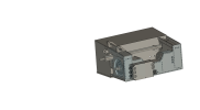
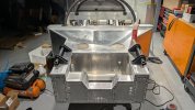
First Picture is the front assembly for holding the drives and suspension. All my slot and tab construction 20+ unique laser cut parts.
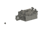
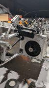
Next is the mock up of the suspension, chain drive, and push rods, ect.
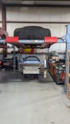
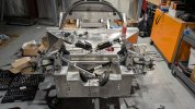
Next is the car striped and ready for assembly.
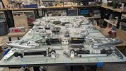
4 is the full suspension system after cnc, waiting to be assembled.
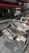
5 is the front assembly on the car. My assembly is more square then the frame! IT is all interesting to note that the pickup point for the lower front suspension are not perfectly centered on my chassis, it off by about 1/8 inch.
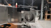
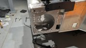
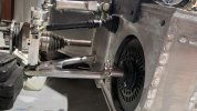
6 is side profile of motor mounting area and the cro-molly torsion spring mount. Note, all parts in black have been cercoated, all aluminum has ben clear coated with ceracoat. I can not say enough good things about ceracoat.
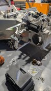
7 close up of the emrax motor mount. The motor eventually will be mounted in double shear.
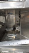
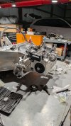
8 Inside on the foot wheel, showing mounting plates.
9 passenger side suspension test mounted.
10. custom upright and C6 hub mounted. (note the upright can use C6 or C7 hubs and ABS)
For those that don't remember, Originally, i was trying to fit two small tesla drive units up front in the car and two LDU units in the rear. The rear was straight forward, and I was able to get them mounted. However, the front end was much more difficult than I expected at first pass. The tesla SDUs failed first for space and second for gearing. As no aftermarket gear sets exist for the small drives, I would have to gear them down and it just took up too much space., or too radical of modifications to the drives to make it work. Next, I did a design using the leaf motors and a chain drive. This worked, but the leaf motor is just too large too, with two of them in the space i have available in the front of the car. But the chain drive idea stuck, and I was able to finally find some axial flux motors that had the power output I needed in a very tight package. These are EMRAX 228 motors and they solved the problem. These motors are used heavily in SAE racing that college teams do, and these is a wealth of knowledge on how to use them with chain drives. Stealing as much as I can from master thesis, and reddit posts, I was finally able to get a design for a front assembly that would mount the motors and give me a 3:1 gear down chain drive for the front wheels.
However, I had to convert the front suspension to a upper A arm push rod setup, and with the torsion bars, hydraulic actuators and air springs for the suspensions system, there was just no way to keep everything withing the fiberglass envelope of the the car. So there will be rocket arms poking through the front clam, but this can be delt with.
I will save you the many many post of the boring process of redesigning basically half the suspensions system, 3d printing 70+ unique parts, making sure they all fit, then cutting them all in metal, and assembly. Needless to say it was a slog, and I learned a hell of a lot. I am now pretty competent at CNC. I am very competent at fusion. I have a solid work flow for designing parts and it takes a fraction of the time to make things then it did 3 years ago.
So here are some pictures of the rough design and how assembly is going. I'm sure there will be questions, happy to answer them.
First Picture is the front assembly for holding the drives and suspension. All my slot and tab construction 20+ unique laser cut parts.
Next is the mock up of the suspension, chain drive, and push rods, ect.
Next is the car striped and ready for assembly.
4 is the full suspension system after cnc, waiting to be assembled.
5 is the front assembly on the car. My assembly is more square then the frame! IT is all interesting to note that the pickup point for the lower front suspension are not perfectly centered on my chassis, it off by about 1/8 inch.
6 is side profile of motor mounting area and the cro-molly torsion spring mount. Note, all parts in black have been cercoated, all aluminum has ben clear coated with ceracoat. I can not say enough good things about ceracoat.
7 close up of the emrax motor mount. The motor eventually will be mounted in double shear.
8 Inside on the foot wheel, showing mounting plates.
9 passenger side suspension test mounted.
10. custom upright and C6 hub mounted. (note the upright can use C6 or C7 hubs and ABS)
Attachments
-
 front box assembly final.png375 KB · Views: 151
 -
 front box working .png473.7 KB · Views: 139
 -
 PXL_20251211_171527602.jpg165.4 KB · Views: 145
 -
 PXL_20251219_143414163.MP.jpg460.4 KB · Views: 143
 -
 PXL_20260124_222058830.jpg392.2 KB · Views: 133
 -
 PXL_20260124_222115612.jpg290.3 KB · Views: 135
 -
 PXL_20260124_222138766.jpg306.7 KB · Views: 118
 -
 PXL_20260201_214149181.jpg120.9 KB · Views: 126
 -
 PXL_20260201_220819259.jpg204.8 KB · Views: 127
 -
 PXL_20260203_183957478.MP.jpg230.5 KB · Views: 153
Holly crap batman, that is an incredible project. A masterpiece!!! keep up the good work. I thought about an electric SLC but it took me more than 3000 hours to build it with the standard LS3 and Graziano. It would have taken me two lifetimes to do what you are doing ") Unless my son moved back to the house, which, thankfully, I dont think it is going to happen LOL. Keep up the good work !!!
Unless my son moved back to the house, which, thankfully, I dont think it is going to happen LOL. Keep up the good work !!!
My son was on the MIT racing team, he worked on the battery management system, I am sure he is familiar with the EMRAX motors, super cool stuff!! I was able to see the car do a few runs, blew me away. Your SLC will be INSANE!!!!
Thank you for sharing your project and please keep posting your progress!!!
Unless my son moved back to the house, which, thankfully, I dont think it is going to happen LOL. Keep up the good work !!!My son was on the MIT racing team, he worked on the battery management system, I am sure he is familiar with the EMRAX motors, super cool stuff!! I was able to see the car do a few runs, blew me away. Your SLC will be INSANE!!!!
Thank you for sharing your project and please keep posting your progress!!!
I have purchased the cells already. Each LDU at peak draw are 1150 amps, and EMRAX pulls 360 all at 400V. That 3020 AMPS @ 400V. Sadly, there just isn't any OEM components that can handle 3000 amps. The max the tesla pyro fuse handles is 2000 amps. So I decided the do a split pack, each side powering 2 motors. I am using the some what controversial Pacifica LG chem cells, mine are all on cold plates, and using a compression sandwich mounting style. Each pack will be 6s2p of these cells good for 1600 amps @ 400V each, which is just enough for a LDU and a EMRAX. The down side of this is each pack will need its own BMS, contactor circuit, fuses, distribution, ect. I will be using a single pack cooling system for both sub packs.
TLDR, Each sub pack will be 31.2 KW, for a combined of 62.4 KW. I expect 25 mins of track driving, or about 160-180 miles of normal street driving range.
TLDR, Each sub pack will be 31.2 KW, for a combined of 62.4 KW. I expect 25 mins of track driving, or about 160-180 miles of normal street driving range.
So motor controllers are a moving target. AEM has a system that does 4 motors, drop in boards for the LDU and out of the box control for cascadia inverters for the EMRAXs. But, the real world feed back on AEM, is poor documentation and poor service. Also, they may discontinue the 4 motor unit. So right now, im leaning to https://dynamlabs.com/ these only do 2 motors, but no boards, runs the drives right out the box. They have the ability modify motor setting based on senor input so in theory i could use two units tied to one accelerator pedal, or a circuit that clones the output of a stock pedal.What are you doing for motor controllers? Tesla? I know my son always talks about how important and diffcult to design those are. Of note , I don't know anything about the subject.
180 miles will be amazing for the level of performance you are getting.
My suspension is going to be run of a Arduino based plc, and it would be nice to have it talking to the vcu's.
that 180 is if you are in a ECO mode on the motors, and doing full charge on the batteries. much more likely, with normal driving and a 80% charge cap 150ish. Teslas with 100 kw pack, weighing 5800 pounds and 1060 hp, get about 240. I hope to come in a 3500 pounds, so the math makes sense.
small update, front end is coming together. test fitting front axels and chain drive clearance. Emrax motors fit like a glove. I fond some high speed, high force electric actuators that i am going to try to replace the hydraulic ones. Linak LA36, these thing can do 1500 pounds @ 20mm/sec dynamic load. pretty good, and really simplifies things.
Attachments
Also, I had a couple people ask about the suspension. The Penske dampers in my setup do not run springs. The springs are torsion bars connecting the two bell cranks. takes about 1 min to change them to stiffer or lighter, and the car does not need to be jacked up to change them. Right now I have 650s in, but I have 750, 850, 950 and 1000's. The air springs allow my to lower the system spring rate in inverse proportion to spring pressure.small update, front end is coming together. test fitting front axels and chain drive clearance. Emrax motors fit like a glove. I fond some high speed, high force electric actuators that i am going to try to replace the hydraulic ones. Linak LA36, these thing can do 1500 pounds @ 20mm/sec dynamic load. pretty good, and really simplifies things.
I am using the spring perch threads to mount a potentiometer which gives me ride height and suspension frequency. That's what the black 3d printed mounts on the dampener are. I am also running small motors w/ hall effect sensors used in 3d sprinters and cnc machines to rotate the dampener and rebound adjusters on the Penske. I should be able to go all 30 clicks in under 0.5 seconds, with precision. Its a hack that gets me electronically adjustable dampeners.
The design is highly customizable.
On could run the system with coil springs on the dampers and not run the second bell crank. This would allow almost any car to have full traditional pushrod and a electric driven front end, for a AWD hybrid setup, like a E-ray, new NSX, or I8, all cars I really like. Small battery and a small generator on the IC motor. Might be hard to fit the battery, but if you gave up 1/2 to 1/3 the gas tank you could probably with a 2kw battery in there.
In my set up you could also scrap the hydraulic actuators and air springs and connect the two forward bell cranks, with or without a damper (for heave) in the middle and get a very tune able roll control by varying the torsion bars. You could also do away with the hydraulic actuators, and run push rods and air springs (and just use them for ride height lift).
Yes, you could also not run the system in an "active mode" with powered actuators (hydraulic or electric or hybrid), and run hydraulic lines front to back and side to side and do a hydraulically coupled roll control like a McClaren F1.
The way the suspension is setup you can make they changes almost on the fly at the track, by changing a few parts you can go from active to a more traditional suspension system.
Oh, and yes they way the system currently is set up I should be able to lift 3 wheels to max height, and retract the 4th and do jack-less wheel swaps, provided the car is not too ass heavy, which I don't think it will be.
The whole idea for this suspension came from the newer GT40 (https://www.motorauthority.com/news...-trick-suspension-has-two-unique-spring-rates) or (
Oh and I straight up stole Scott's idea for variable motion ratios on the bell cranks, why no one did that unit him, I do not know why. Genius. I want to change the rear end geometry like he did too, just amazing work.
To my knowledge it is the first system anywhere, and I mean anywhere, not FASE, not F1, not even R&D papers to give fully decoupled roll control, variable spring rate, and variable ride height. I hope it actually all works.
If anyone wants to try it out, I will probably post all the CAD files on a github at some point. I need to make some call changes to them as I find small mistakes I made during assembly.
Bob
Similar threads
- Replies
- 21
- Views
- 2K
- Replies
- 14
- Views
- 1K
- Replies
- 17
- Views
- 1K