8 stack throttle linkages

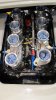
Having just had the 8 stack injection set up better we found that the throttle bodies were only opening at 35 percent, there better now at 65 percent but obviously need to be 100 percent.
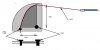
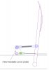
The existing pedal can't really be altered so is there a suitable linkage system available and has anyone else had this problem.
I know it can be solved but asking this question here may speed things up.
Any advise welcome

Engine 302
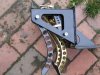
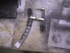
Cable at present from the back to a standard 8 stack t shaped pivot arm
 

Randy V

Moderator-Admin
Staff member
Admin
Lifetime Supporter
Pictures would help us help you Keith...

Usually you can move the cable connection point on the bellcrank closer to the center (fulcrum) pivot which would give you more throttle movement at the carbs/throttle bodies.
But note that this will really quicken the action of the system overall and you will be applying much more throttle per given distance that the foot pedal moves..

--edit--

You may also want to consider replacing the T bellcrank with a cam shaped pulley that the cable wraps around. The pivot location and shape of the cam can quicken or slow down the reaction of the throttle at either end of its travel.
 
Last edited:
Hi Randy, here's the best picture I can find at the moment. I was only getting 35% so drilled a 6mm hole in the pivot arm and relocated the cable fixing , as you say closer to the fulcrum this allowed the throttles to open to 65% but can't appear to do any more with this linkage.
 

Attachments

  • IMG_1435_0612.jpg
    IMG_1435_0612.jpg
    80.6 KB · Views: 670
Kieth.
The other thing you can do is to change the connection on the throttle pedal. If you have moved the fulcrum on the injector end you may want to move the pedal connection higher on the pedal. This should cause the cable to be extended further out of its sheath and thus more movement at the injectors. It just a geometry problem. It may alow you to move the injector end back where it started from.

Bill
 
Not the prefered option to move the connection point on the pedal Bill it would be best on the engine end.
 

Ian Anderson

Lifetime Supporter
How about an interim fulcrum near the inlet manifold where the throttle cable draws on a pivot arm and at the top of the pivot arm connects to your throttle bodies. With a turnbuckle type connector to take up any slack

By adjusting the length of the fulcrum you could adjust it to get maximum throttle opening at full pedal travel.

Ian
 

Randy V

Moderator-Admin
Staff member
Admin
Lifetime Supporter
attachment.php
Keith,
In this picture it appears that your cable could be moved over to the left side and you would gain a fair amount of additional movement for your troubles..

Bill is correct in that you may also need to move the connection point at the pedal - and we all know what it means to tell someone to go "down there" on a GT40...
 

Mike Pass

Supporter
Some years ago we had a race chevvy that was a bit "sudden" in it's torque delivery. We used a thing called a snail cam. This gives a slow rate at first and then this speeds up as the cam rotates. You make a 1/8" ali sheet cam which is curved so that the cable pulls at a big distance from the pivot as the throttle is first opened and then the distance to the pivot gets less and less. This gives a variable rate of throttle opening. We made several shapes from 1/8 sheet ali and then sandwiched them between two more ali discs with small bolts to form a groove for the cable to run in. It is easy to make different profiles until you get the rate and 100% throttle. The initial slow opening makes the car more driveable.
Cheers
Mike
 
Hi Keith,
I think if you space your two link arms further apart you will acheive better opening.
Randys right to you need to be pulling closer to a right angle at the arm.
I made a wheel for my cable to pull around and it works great,check out my entry under induction manifold with throttle bodies.

cheers Ali
 
Hi Mike, I am trying to visualise your snail cam throttle, as I can think of a use for that on my project ,any chance of a quick sketch to explain.
Regards
Graeme
 

Mike Pass

Supporter
The snail cam is made up from 3 pieces of ali sheet sandwiched together and glued/rivetted etc.. The middle one is shaped like the pic. The length of the sides of the odd shape in the middle can be adjusted to give the rate you want and the overall full opening distance. The cable runs in the slot formed by the two outer sheets.
Hope this makes it a bit clearer.
Cheers
Mike
 

Attachments

  • Throttle snail cam.jpg
    Throttle snail cam.jpg
    60.2 KB · Views: 889
Thanks Mike, I think I get it now, its the same as most oem cars have, I always thought the reason for the curve was to give the cable a bigger arch of surface area so the wire did not frey. Many thanks for the picture.
 
You can make a very progressive linkage by using an intermediate pivoted plate. The initial movement of the pedal results in very little movement at the cable. It's all a matter of sizing and angles.
 

Attachments

  • throttle_pivot.jpg
    throttle_pivot.jpg
    74.6 KB · Views: 505
Last edited:
Back
Top