DCraig
CURRENTLY BANNED
April 29, 2007
Porsche Transmission tools to set pinion depth; back lash; shim pack.
The 385 tool is a must have to set the transaxle up correctly. White lead, dykem, and case works drilled to place dial indicators through are closely akin to pissing in the wind. Even so, lots of "professional" transmission shops set them by guess and by golly. Sometimes they can get away with it. :squint:
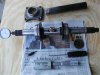
Picture:
Top left is the needle bearing O.D. "drop through" gauge.
Top right is the needle bearing I.D "drop over" gauge.
The long bar with dial indicator and cone shaped locators is the 385 tool.
Just under it on the right is the magnetic flat plate.
Just under it on the left is the plunger tool that transmits the measurement from ring gear dead center to pinion shaft end to the dial indicator.
To the right of it is a long reach 3MM allen to secure the cones into the main carrier bearings.
On the bottom is the micrometer used to check back lash on ring and pinion as well as individual gears.
Just for grins I placed the tool set on today’s newspaper with my finger ring on the 385 plunger port. I have often asked an "expert" to send a picture of his 385 tool and more than once I have received a picture taken out of the Baum or Zelinda catalog. The newspaper could be duplicated at any time after today but that 2500 year old Shaolin ring might present a problem. :lol:
Since I just set up a 935 gear box this morning (same set up as a 930 box) I will take you through the procedure using the dimensions from this one.
Drive Pinion:
There are two numbers scribed on the flat end of the pinion gear face.
The first number (N*) describes the deviation from the end of the pinion to the dead center of the ring gear. This is known as the radius deviation and is specific to this ring and pinion set. It is marked 1- 10 on factory vehicle boxes and 1- 20 on race car boxes. Today’s pinion was marked N2
so I know that the deviation is 0.02mm.
The other number is the match number and it is also found on the ring gear. This set’s match number was 654.
Ring Gear:
One number is the match number as described above and it too is 654.
The other number is the back lash number and on this ring it was marked 0.15. This is deemed the ideal number for this set's quiet running.
Factory design dimension on a 930/935 gear box is R = 82.29.
Add deviation number r = 0.02
This gives me the adjustment dimension "E" = 82.31
Setting pinion depth:
I set my dial indicator to the adjusted R value I got above of 82.31
Next I measured the pinion depth without shims and got -0.14mm
The distance of the pinion face was = 82.15
Taking the total of 82.31
And subtracting the depth without shims gives me - 82.15
Tells me that I needed = 0.16mm in shims
The shims come in thicknesses of: 0.10mm; 0.15mm; and 0.20mm
I added a 0.15mm shim that put me within the permissible range +or- 0.03mm
After the shims are added the depth must be checked again to verify.
Setting the ring gear back lash:
S1 is the ring gear side of the differential.
S2 is the opposite side.
Shims are located under each one of the main carrier bearings.
The backlash tolerance is set by adding shims to the S2 side with no shims on the S1 side until a preload of 56 kpcm is attained with the differential cover torqued into position.
Then shims are pulled out from the S2 side and added to the S1 side (moving the ring gear closer to the pinion shaft) until the back lash is within specs of 0.16mm to 0.20mm.
It may look daunting at first but there is a lot of gray matter on this board. I never posted anything like this on Porsche, Mercedes, or Ferrari boards. In fact, I quit all participation in PCA, POC, FCA, and MBCA due to my allegy concerning a$$holes. :loser:
I taught transmissions to about 200 mechanics and only two of those just didn’t get it because, like most people, they were awed by the very sight of an open gear box and they didn’t know the basic facts that gears stay in constant mesh. It all became clear when they realized that the shift fork pushed the slider over the guide sleeve until the engagement teeth on the slider locked onto the engagement teeth on the gear, thus transferring the torque from the input shaft to the pinion shaft. The synchro rings are there to equalize the speed of the gear and the slider. The grinding noise comes from worn synchros that fail to properly equalize the abovementioned speed differentials.
I hope this helps, eh?
DC
Porsche Transmission tools to set pinion depth; back lash; shim pack.
The 385 tool is a must have to set the transaxle up correctly. White lead, dykem, and case works drilled to place dial indicators through are closely akin to pissing in the wind. Even so, lots of "professional" transmission shops set them by guess and by golly. Sometimes they can get away with it. :squint:
Picture:
Top left is the needle bearing O.D. "drop through" gauge.
Top right is the needle bearing I.D "drop over" gauge.
The long bar with dial indicator and cone shaped locators is the 385 tool.
Just under it on the right is the magnetic flat plate.
Just under it on the left is the plunger tool that transmits the measurement from ring gear dead center to pinion shaft end to the dial indicator.
To the right of it is a long reach 3MM allen to secure the cones into the main carrier bearings.
On the bottom is the micrometer used to check back lash on ring and pinion as well as individual gears.
Just for grins I placed the tool set on today’s newspaper with my finger ring on the 385 plunger port. I have often asked an "expert" to send a picture of his 385 tool and more than once I have received a picture taken out of the Baum or Zelinda catalog. The newspaper could be duplicated at any time after today but that 2500 year old Shaolin ring might present a problem. :lol:
Since I just set up a 935 gear box this morning (same set up as a 930 box) I will take you through the procedure using the dimensions from this one.
Drive Pinion:
There are two numbers scribed on the flat end of the pinion gear face.
The first number (N*) describes the deviation from the end of the pinion to the dead center of the ring gear. This is known as the radius deviation and is specific to this ring and pinion set. It is marked 1- 10 on factory vehicle boxes and 1- 20 on race car boxes. Today’s pinion was marked N2
so I know that the deviation is 0.02mm.
The other number is the match number and it is also found on the ring gear. This set’s match number was 654.
Ring Gear:
One number is the match number as described above and it too is 654.
The other number is the back lash number and on this ring it was marked 0.15. This is deemed the ideal number for this set's quiet running.
Factory design dimension on a 930/935 gear box is R = 82.29.
Add deviation number r = 0.02
This gives me the adjustment dimension "E" = 82.31
Setting pinion depth:
I set my dial indicator to the adjusted R value I got above of 82.31
Next I measured the pinion depth without shims and got -0.14mm
The distance of the pinion face was = 82.15
Taking the total of 82.31
And subtracting the depth without shims gives me - 82.15
Tells me that I needed = 0.16mm in shims
The shims come in thicknesses of: 0.10mm; 0.15mm; and 0.20mm
I added a 0.15mm shim that put me within the permissible range +or- 0.03mm
After the shims are added the depth must be checked again to verify.
Setting the ring gear back lash:
S1 is the ring gear side of the differential.
S2 is the opposite side.
Shims are located under each one of the main carrier bearings.
The backlash tolerance is set by adding shims to the S2 side with no shims on the S1 side until a preload of 56 kpcm is attained with the differential cover torqued into position.
Then shims are pulled out from the S2 side and added to the S1 side (moving the ring gear closer to the pinion shaft) until the back lash is within specs of 0.16mm to 0.20mm.
It may look daunting at first but there is a lot of gray matter on this board. I never posted anything like this on Porsche, Mercedes, or Ferrari boards. In fact, I quit all participation in PCA, POC, FCA, and MBCA due to my allegy concerning a$$holes. :loser:
I taught transmissions to about 200 mechanics and only two of those just didn’t get it because, like most people, they were awed by the very sight of an open gear box and they didn’t know the basic facts that gears stay in constant mesh. It all became clear when they realized that the shift fork pushed the slider over the guide sleeve until the engagement teeth on the slider locked onto the engagement teeth on the gear, thus transferring the torque from the input shaft to the pinion shaft. The synchro rings are there to equalize the speed of the gear and the slider. The grinding noise comes from worn synchros that fail to properly equalize the abovementioned speed differentials.
I hope this helps, eh?
DC