All I can Bob, is Holy Crap, I’m impressed. The amount of thought and engineering going into this project just blows me away.
Excellent job !!!
Regards Brian
Excellent job !!!
Regards Brian

 ehfcv.com
At one point back in the late '70s, I seriously considered using a hydraulic suspension system. I had a DC motor- driven hydraulic pump with a Moog servo valve that I thought would do the job. The key was to limit the stroke to as small as possible so as to limit the HP required from the pump and to increase the frequency response of the servo system. I finally realized that this was an infinite time and money pit so I just used a good software package to design a conventional suspension.Sourcing/building actuators for the suspension system. When I started designing the suspension system for this car almost 6 years ago now, there were not too many examples of active suspension systems using mechanical actuators.
The over all idea in these systems is that you place a actuator in between the wheel and the body and use it to compensate for forces on the car and/or travel of the wheel. In a ideal form these systems could theoretically replace springs and dampeners, and keep perfect tire contact with the road service. In practice, as with most things, this is very hard to do. Two things have mostly held up the broad adoption of these systems, the first is operating frequency of the system, which generally needs to be greater that 50 Hz (50 times a second). The second is the speed/force of the actuator, which needs to at least be able to push with the force seen on the tire, and ideally 2-3x, more importantly it needs to be able to move fast enough. For body roll control you need 2-4 inch/sec, and for wheel control you need >10-15 inch per second. These are pretty aggressive numbers for most off the shelf hydraulics/electric actuators, where movement rates are more like 0.5-1 inch/second.
In my research I found a few systems that had data I could bench mark off.
The grand daddy of them all, Williams FW14 F1.This is the system most people know about, but very little details of the system are public. This is really a body roll control system, it was programable to the track it was running on, and adjusted body position for optimal performance on each corner and straight. You can tell looking at the actuators they are really small, with little travel, and just looking at the system in demos, the body does not move that fast. I think I read somewhere that it had ~5 inch/sec of movement @ 10Hz.
The BOSE system.This system is truly fully active and adaptive. It used electro actuators and computer control to basically do away with springs. vertical movement of the actuator at reported 50 in/sec and operating frequency of 15-50 Hz back in the late 90's and early 00s Lots of information on the system out there and why it never got adapted to racing. It was ok for road cars, but not worth the weight for racing. The core of this system is now being seen in modern Chinese cars like the BYD U9 and the Nino...I will show so videos of its action, very impressive.
The German FSAE team.andWhile not a active system, this team built a fully decoupled body roll system using hydraulics. When you watch the videos of their car, you start to understand the power of these systems, even if we are just addressing body roll.
When you start to think about it, suspension systems on cars are incredibly out of date compared to improvements in almost all other aspects of a vehicle. I think suspension is going to be the next really big differentiator for cars, as HP and torque become pretty much the same for every model. Right now 700 HP is nothing these day, and 0-60's under 3 are the norm. Moreover, in the EV world, most cars a traction limited, HP and torque are available in such excess that speed now really depends on tires and suspension. Gas cars are also converging on this singularity too, but are probably 5 years behind. All that said, I know right now this suspension system seems over kill, just wait in a few years active is going to be the way forward.
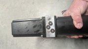
I went in to this designing this system without any off the shelf solutions that would get me anywhere near even 5 inch per second, 2000 pounds of force, and 10Hz. I put the smallest diameter hydraulic actuators I could find that would give me the 2000 pounds of force I need (1 inch bore/0.68 stroke), and assumed over time, technology would trickle down, or at the very least I could do a traditional spool based system and try to get the hysteresis down to a point it would all work. Over the last 6 years, a lot has happened in the active suspension space, but nothing off the shelf has trickled down yet. The big systems that came out that have guided my design, are the following.
Porsche Active Ride system. () Hydraulic system operating at 800V, 10-13 Hz, 2000 pounds, 2inch/sec (I think).
https://newsroom.porsche.com/.imagi...ort/b-technik2.jpg/jcr:content/b-technik2.jpg
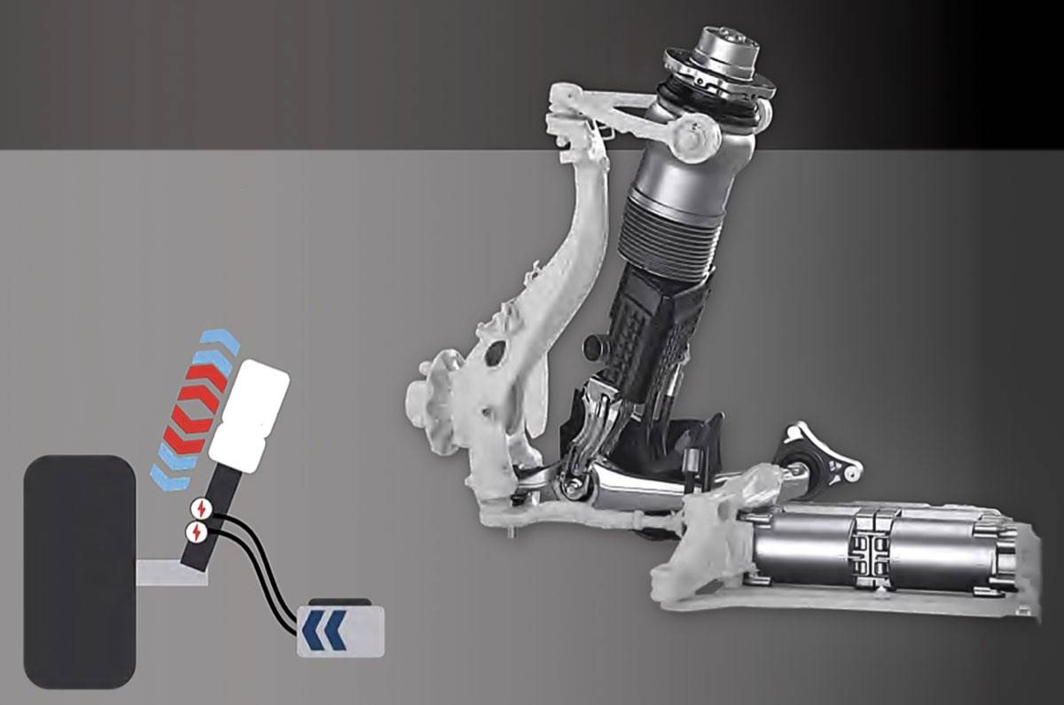
2024 Porsche Panamera with Porsche Active Ride (G3) Suspension System | EHFCV
The innovative Porsche Active Ride active suspension system is available as an option for the E-Hybrid models of the new Panamera.
System is a 4x bidirectional hydraulic pumps with 400-800v 1800 watt BLDC motor attached to each actuator. Look at the speed that the body responds to the phone, and compare it to the next two systems.
BYD U9 now things get interesting. This is basically a modernized version of the BOSE system, that was sold to ClearMotion. https://www.youtube.com/watch?v=MGCz4Tdr90U&t=76s Notice how much crisper and fast the movements are in response to the phone tilt. Also....the bunny hop is just nuts. Apparently this is a 4.5 KW nominal, 9kw peak bldc motor attached to a hydraulic pump, i assume its 800V, but i can not confirm that. It operates at 100 Hz and 500 mm/sec (19.6 inch/sec) This car just took the EV production car record Nuremburg lap time.
Finally, Nio ET9 another Chinese car, this one is using the clearmotion suspension. https://www.youtube.com/watch?v=SBXglXufprw see how fast the car can rock. https://www.youtube.com/watch?v=G8Ih9ALYo_Y showing the response of the suspension system. This is a 1000 Hz system, but only a 2 inch/sec system. I could not find the power output.
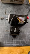
I designed my system in anticipation that I could not source or make a actuator that could do >10 inch/sec., so I am using traditional dampening and springs. If anyone know of small hydraulic pumps or actuators that might work, Im all ears. As is, my active system will be more like Williams/Porsche body control systems. With that in mind, I went out and started buying small hydraulic pumps.
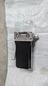
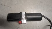
First one: was the HS10-350 its about 1.1L/min bidirectional output @ 15 mpa. https://www.ebay.com/itm/316076660015. This would get me about 1.4 Inch/sec stock at 24v.
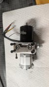
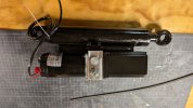
Second one: is part of a 2" bore cylinder https://www.ebay.com/itm/147148211496 1.8L/min, 25 mpa, 12V 800 watt. This would get me 2.5 inch/sec at 12V.
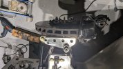
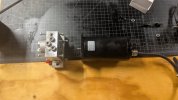
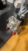
Neither is going to get me to where I need to be stock. So i disassembled them with the goal of swapping to motor to a BLDC motor of much higher power (https://shop.odriverobotics.com/products/odrive-custom-motor-d6374-150kv) 5.3 Kw peak, 2.6 Kw continuous power, 6500 RPM @ 58 volt. I would love to use a 400V motor, but I can find a small 5kw 400v bldc. Again, I'm open to suggestions. The advantage of using a smaller BLDC is i can use the Odrive ESC/controller which allows CAN control @ 8000 Hz, they use these things for drones and balancing robots.
My plan right now is to use the BLDC motor on the larger stripped down hydraulic pack with the 0.65 cc head and run it at 6000 RPM, and that should get me a solid 5 inch/sec extend rate. I may try to source a 1.25 cc bidirectional gear head and see if I can get 10 inch per second, but it going to take more work to source the gear head.
I'm open to any recommendations if anyone out there has hydraulic experience.
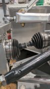
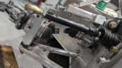
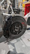
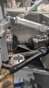
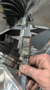

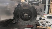
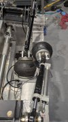
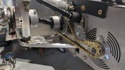
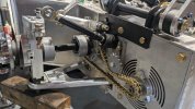
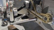
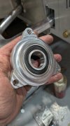
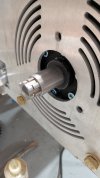
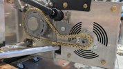
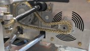
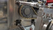
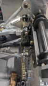
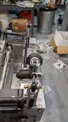
What is the chain drive?fitted everything yesterday. looks like it all works. 930 cv joints. axle worked out to be 4" spline to spline. Air-ed up the bags for the first time, at they expanded much more than the spec sheet says they should, almost 8 inches! realized i fundamentally didn't understand how these things work, and that they need a constraint/cage to limit deflection and max/min expansion/compression. For my bags its 4.5 inch max/ 2 inch stroke. So working on constraint system now.