CANAMSA - SA stratch build

Is this some sort of 3-axis router?
I have done something like this before but used a vertical CNC mill, but the table was small which required me to divide my part up into many smaller sections.

I would be interested to know what this machine is, looks much more cost effective then a vertical mill!

Is that just hardware store foam your using?

try CNCZONE, or google "diy cnc" heaps of options for making your own.

I’ve been looking into this recently, see http://www.oz-clubbies.com/forums/index.php?showtopic=7047

I’m trying to work out how big I can make the machine and still get it to work properly.


Sorry for the Hi-jack this should be started as another thread.

Keep up the good work Fred. It is really starting to come along.
 
Hi guys, thanks for responses.

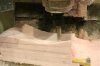
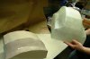
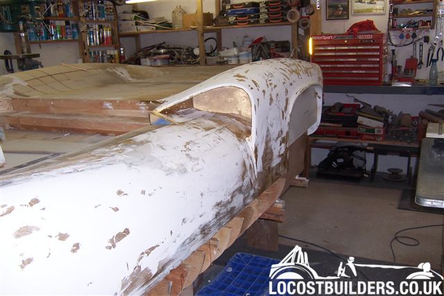
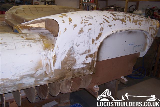
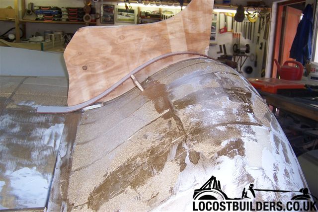
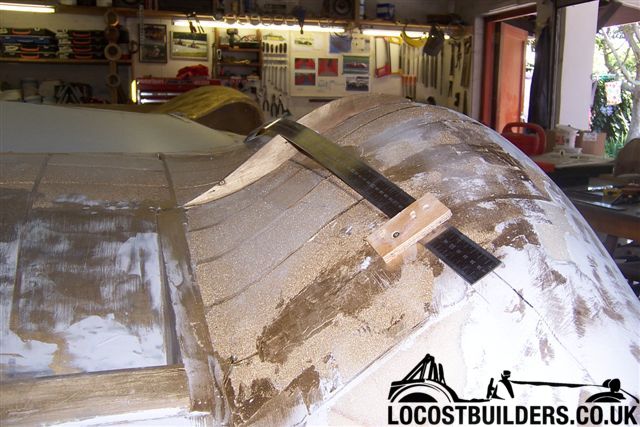
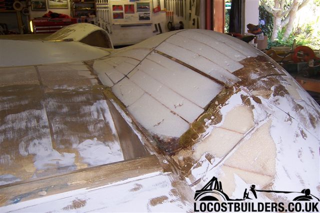
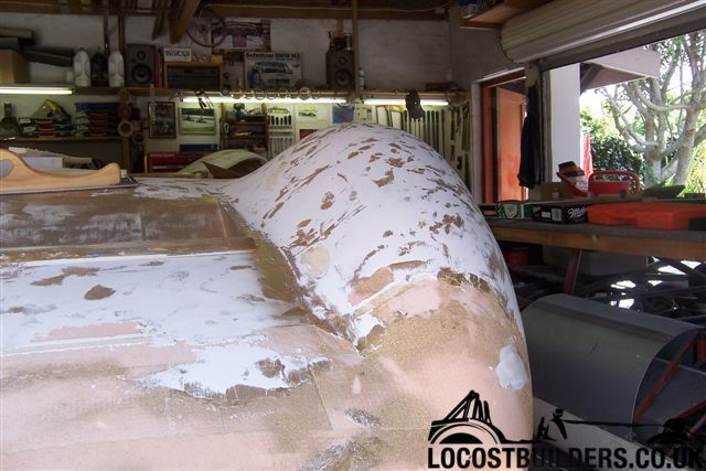
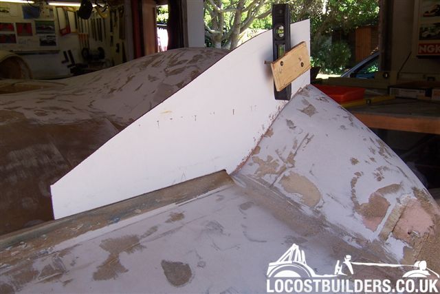
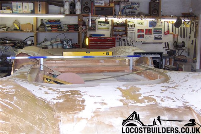
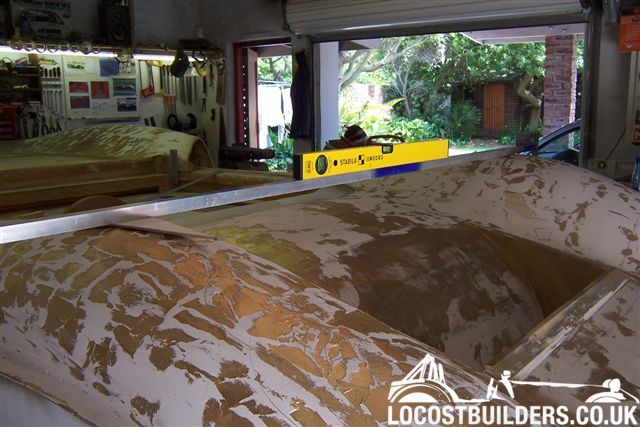
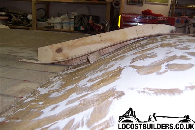
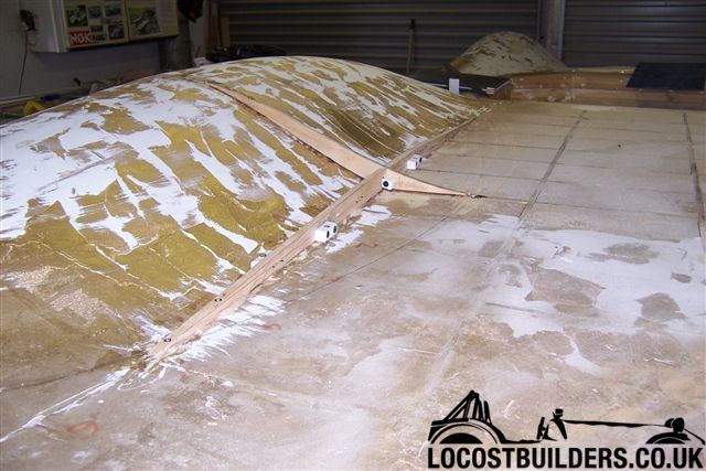
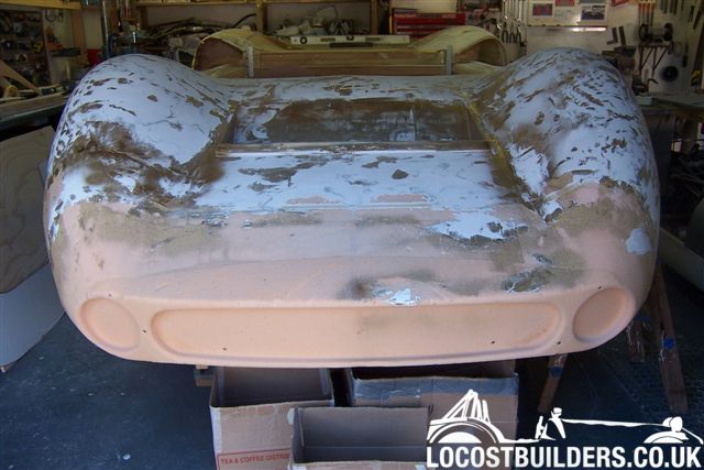
The filler you see is interior grade plaster filler (brand name "polyfiller") over the foam in areas where I am reworking and cutting into the foam between ribs, in order to see the finished shape , before I put the GRP skin on. My logic is that it is easier and cheaper to shape foam and plaster filler before skinning, rather than resin and body filler after skinning.


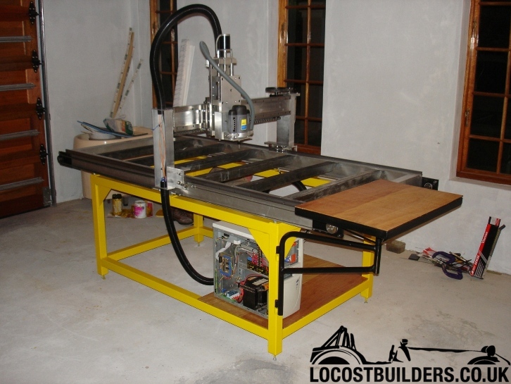
The 3-axis router is a machine my friend Andrew made in his garage at home. I attach a picture. It still needs dust guards and an extraction system.
It makes small parts in foam, wood and even aluminium to a tolerance of about +- 0.05mm. It's pretty basic but good enough for what we are doing.

Some info:
He used stepper motors on all 3 axes and drives them with 10th microstep drives from Gecko. The X and Y axis are actuated by standard off the shelf 06B plate link chains. Reduction from the stepper to the linear axis drive is achieved by a VW golf cam pulley (44 teeth L-pitch) and a 14 teeth pulley. The linear rail moment is on ball bearings running on bright mild steel bar that's bolted to ally extrusions. The PC Controller is Mach 3 from Artsoft at New Page 1. This can handle up to 6 axis.

He draws parts in Inventor or AutoCAD, 3d models are converted to .stl format for the cam package (Visual Mill 5) to accept. Visual mill will accept 2d .dxf files as well. Visual Mill takes the drawing or model and the milling tool dimensions that Andrew specifies to generate a path that the tool must follow to achieve the desired shape. This Path is described in G-Code, basically a text file. The router controller can interpret this G-code and move the X, Y and Z axes accordingly. It can do X Y and Z simultaneous interpolations.

The cutting tool is an ordinary wood router with a speed control added, you can turn it right down for foam and it just makes a soft crushing noise, but with ally you have to run it flat out and the noise is definitely not neighbour friendly.


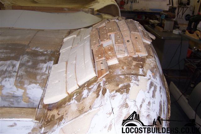
The foam we used is polyurethane foam, with a density of about 32 kg/m2, used in the insulation industry. That density is not ideal, heavier would be better.


Cheers

Fred W B


DSC02920.JPG
 
I did this one a while back; this was a part of a mold to a seat. You can’t tell from the pic, but the overall length of the piece was something like 16” long.
Its made from that pink foam you find at hardware store for insulation. The pink stuff works better then the blue. The best would be that tooling board or foam suggested by Mr. Just, but that stuff it’s pretty expensive. I recommend using the biggest tool that you have at the highest speed to get those cutting speeds really high. The high cutting speeds leave really nice edges, slow speeds tend to tear and rip at the foam leaving a ratty edge. I would then seal it in epoxy resin (cant use polyester on foam!) and use bondo to fill it and smooth it out. After that’s done, I would give it another coat or resin to be polished to make a good surface for mold release.


The other pic is a shroud for a very small heat exchange done the same way.

This should probably be in a different forum.
 

Attachments

  • foamcut.jpg
    foamcut.jpg
    48.1 KB · Views: 1,293
  • cnc-shroud.jpg
    cnc-shroud.jpg
    29.7 KB · Views: 1,299
hi, yes the sika-foam i expensive, but you can by it in variable weights and different hard, you can work on it with normal polyesther resin, it is aceton-save heat-save-resistant, you can filler it with most polyesther-fillers, it is a closed cell foam so you can use it in marineaplicatones, you can sand(grind) it high to a p500 sand-paper, so you save so much time and can do so precise work, it is unbeliveable.
and in usa must be other, not so expensive foam-companies, i use it the first time in usa, in a motocycle race team, 12 years ago.

TEAM JUST
 
Fred,

I just came across this thread a few days ago thanks to the link provided by Chris Kouba. Amazing job you are doing on this project.
 
Hi Guys, thanks for the interest.

I have taken advantage of some leave over the holiday season to get some quality time in the garage, between family commitments and eating!

bb%200004.jpg
 
I have been working on the RHS, to get it the same as the reworked LHS. Where I have deviated from the original routed stations, I have to make templates to check symmetry of the profile on the LH and RH sides.
canamsa%20body%20jan%2008%20200.jpg


canamsa%20body%20jan%2008%20202.jpg
 
Last edited:
You have to be sure to keep the template vertical when checking, particularly where the body slope is steep, hence the spirit level attached to this template.

canamsa%20body%20jan%2008%20204.jpg
 
In order to keep the body as symmetrical and "square" as possible, I check everything back to a horizontal reference plane I have across the back of the cockpit. Have to be careful you don't loose the centerline on the pattern!
canamsa%20body%20jan%2008%20180.jpg
 
Here you can see that at this point I determined that I had had to bring the highest point of the RHS front wheel arch hump up another 3 mm.

canamsa%20body%20jan%2008%20280.jpg
 
Last edited:
Have now started adding a bit more "fat" to the rear wheel arch humps towards the center of the rear deck.
canamsa%20body%20jan%2008%20290.jpg

canamsa%20body%20jan%2008%20300.jpg


Finally starting to feel I have now broken the back of most the body shaping.

Cheers

Fred W B
 
Hi Johan

Thanks for the very kind words. They are particularly appreciated coming from you as an owner of originals. I have been lurking a bit on the Lola heritage forum but am apprehensive about posting there as it seems that some owners of some original cars (not necessarly Lola's) can get really worked up about replicas, particularly when they are not 100% correct.

If you think it will go down well I will post a shorter version of the story so far up there.

Cheers

Fred W B

I so wish you would post a version of this on lola Heritage...
It is very interesting and I for one am enthusiastic about your progress. It would have been so easy to just get or copy an original body, but much more interesting to watch you develop your interpretation.
 
Back
Top