
You are using an out of date browser. It may not display this or other websites correctly.
You should upgrade or use an alternative browser.
You should upgrade or use an alternative browser.
CAV - Getting the Horsepower to the Ground - Part V
- Thread starter bchildress
- Start date
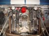
If you compare this picture to the one from Ian, you can see a difference in the basic size of the distributors between the two cars but the engine block locations are about the same.
I will need to fabricate a fire proof metal engine bulkhead cover and space it forward a bit to accommodate the new engine position but there is plenty of room behind the seats of the CAV.
I will need to fabricate a fire proof metal engine bulkhead cover and space it forward a bit to accommodate the new engine position but there is plenty of room behind the seats of the CAV.
Attachments
") Good idea as these babies get REAL LOUD above 3000rpm...
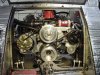
Good idea as these babies get REAL LOUD above 3000rpm...The third and last detail I will mention in Part V is also a direct result of a suggestion given to me by Ian. The lower water pump hose on many CAV cars is one of those universal pleated hoses that allow it to flex in all directions. Ian has suggested that it be replaced with a smooth side molded hose to minimize water turbulence (CAVitation? [joke]). In this early picture, my engine is in standard position and with the original pleated hose but in the last few months I have noticed many brands of cars using the same type of pleated hose.
Attachments
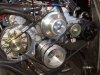
The original hose flange angle only needed a straight hose with a 30 bend. From this picture of the oil pan and leveling string you can also see how misaligned the hose flanges have become since I repositioned engine. Now that my engine is as low and forward in the car as it can go, I set about looking for a hose to do the job.
Attachments
Re: CAV - Getting the Horsepower to the Ground - Part V *DELETED*
Post deleted by Gary Gibbs
Post deleted by Gary Gibbs
Gary,
Deja vu back at you. I have seen this picture before but could not read the labels or follow the re-routeing of the radiator hoses, especially the relocation of the 3-way connection that is usually inside the passenger side pod. I remember that you did this to improve cooling and control high RPM pressure. Any chance of getting you to start a post with a before and after diagram and a short tutorial?
---------------------------------------------------------------------------------------------------
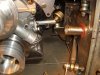
With the engine now 1 1/2 inches down and 1 1/4 inches forward I needed a hose with a three-dimensional over-center J-bend and a jog forward. Try telling that to the guy at the auto parts counter! Eventually I convinced a few stores to just let me look through their inventory. I found the exact diameter and angle piece I needed on one end of a longer piece of molded hose.
Deja vu back at you. I have seen this picture before but could not read the labels or follow the re-routeing of the radiator hoses, especially the relocation of the 3-way connection that is usually inside the passenger side pod. I remember that you did this to improve cooling and control high RPM pressure. Any chance of getting you to start a post with a before and after diagram and a short tutorial?
---------------------------------------------------------------------------------------------------
With the engine now 1 1/2 inches down and 1 1/4 inches forward I needed a hose with a three-dimensional over-center J-bend and a jog forward. Try telling that to the guy at the auto parts counter! Eventually I convinced a few stores to just let me look through their inventory. I found the exact diameter and angle piece I needed on one end of a longer piece of molded hose.
Attachments
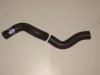
I bought the big piece and then cut off the end that I needed. I think at least one of the many
angles on this extra long hose would work even if the engine of your CAV is in the stock position.
This hose is CarQuest, P/N #22042, bar code 0-72053-41419-6. Gary Gibbs also used a CarQuest hose
and he may have an alternate hose and part number.
angles on this extra long hose would work even if the engine of your CAV is in the stock position.
This hose is CarQuest, P/N #22042, bar code 0-72053-41419-6. Gary Gibbs also used a CarQuest hose
and he may have an alternate hose and part number.
Attachments
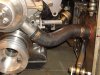
Independent of the content of this thread, you can sure appreciate how hard it is to get a picture
of the front of the engine. The combination of short focal length, wide angle, and good depth of
field is a killer !
--------------------------------------------------------------------------------
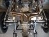
The real benefits from relocating the engine were improvement to fore and aft weight distribution
and a lower center of gravity. I always like it however when I get a few other side benefits.
The following picture shows the ZF half shafts now almost straight and level. There have been a
number of posts about this lately. Most farm, factory, and stationary equipment always includes
an offset in CV and Universal Joints drive shafts because it makes the shafts last longer than one
perfectly aligned. In a car where the drive shaft naturally moves around with suspension travel,
I do not think it matters. Having the shafts straight and aligned in a GT40 is probably more
cosmetic than function but every detail counts.
The next part of this project (Part VI) will be either the final anchoring of the ZF transmission
or the how inflated sheep bladders may be employed in an air ride suspension. It is impossible to
know ahead of time which job will be the biggest mess but I do have a friend in Scotland that I can
go to for advice. In either case, alignment is sure to be critical.
of the front of the engine. The combination of short focal length, wide angle, and good depth of
field is a killer !
--------------------------------------------------------------------------------
The real benefits from relocating the engine were improvement to fore and aft weight distribution
and a lower center of gravity. I always like it however when I get a few other side benefits.
The following picture shows the ZF half shafts now almost straight and level. There have been a
number of posts about this lately. Most farm, factory, and stationary equipment always includes
an offset in CV and Universal Joints drive shafts because it makes the shafts last longer than one
perfectly aligned. In a car where the drive shaft naturally moves around with suspension travel,
I do not think it matters. Having the shafts straight and aligned in a GT40 is probably more
cosmetic than function but every detail counts.
The next part of this project (Part VI) will be either the final anchoring of the ZF transmission
or the how inflated sheep bladders may be employed in an air ride suspension. It is impossible to
know ahead of time which job will be the biggest mess but I do have a friend in Scotland that I can
go to for advice. In either case, alignment is sure to be critical.
Attachments
What Ron said. It's particularly valuable to me as I'm in the engine-fitting stage of my build. Unless you're very experienced builder or really smart, you probably won't figure this stuff out until you try to fit things up and run into problems. Excellent thread.
Just one thing...Bob, can you re-size that big picture? I'm viewing at 1280 x 1024 and I have to keep scrolling back and forth to read the comments.
Just one thing...Bob, can you re-size that big picture? I'm viewing at 1280 x 1024 and I have to keep scrolling back and forth to read the comments.
Hi Mark and Ron,
Thank you both for your encouragement.
Not everybody is totally high tech but I am glad
my intermediate technology threads contribute something
perceived as useful and interesting to the Forum.
As for the run away margins, this is an artifact of the Forum
when anyone posts an oversize picture like the big picture from Gary.
Unless Ron can reformat, the only way I have found to maintain
a reasonable right margin is to add hard breaks
before the words run off the edge of the screen.
Hey Ken,
I will be happy to send you a lot of details and pictures but they
don't really add much general informaiton this thread so
watch your personal email for the information.
Bob
Ross Nicol
GT40s Supporter
Hi Bob
I've just received my new ZF and as it has the ears on top I have to redesign my mounting.I also want to allow some room for the roll bar to pass along the rear of the crossmember.I've just spent some time studying your setup and it appears you have rubber engine mounts and solid mounting of the ZF via bolts through the crossmember? Was this intentional? I would say the engine mount rubber Isolation would be negated by the solidly mounted trans.Not trying to be a smart ass, just thought I'd point it out.I agree with the others, well done detailing your work, I try but don't have the time to post anything more than bits and pieces.
Regards Ross
Hi Ross et al,
Your critiques are always welcomed and good luck with your design work. If you need any specific pictures or measurements from me I would be glad to do a direct email. I ended this thread by saying that Part VI would be about the final anchoring of the transmission. I am now designing a support for the ZF, so you and I are on the same job at the same time. By coincidence, Dave Briggs and I have just traded a few emails about this very subject.
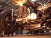
As for the connection of the ZF to the tubes that stick out from the crossmember, the tubes on my car are thick wall stainless steel with pressed in rubber bushings. A smaller 1/2 inch I.D. tube runs through the center of the bushings from end to end so this is not a hard bolted connection. (See Part II for pictures before the polyurethane bushings were replaced with rubber.) Stock CAVs use a similar method at the crossmember like Gary said.
However, original cars have motor mounts, dog ears on top of the ZF, and two heavy duty motor mount like bushings on the bottom sides of the bell housing. I would like my motor and transmission to be anchored equally well.
I am trying to retain the stock CAV rear frame and just design a simple add on bracket to support some of the transmission weight and minimize the waggle at the end of the transmission during hard cornering. Of course the hard parts are accommodating the right side of the ZF with the protruding shift mechanism box and strengthen the tubing under the transmission so it will support the load.
I will start Part VI in April but in the mean time I would appreciate anyone willing to email me a picture of their transmission mounts so I can see how others have solved the problem (or maybe start a thread for transmission mount pictures).
Bob
Your critiques are always welcomed and good luck with your design work. If you need any specific pictures or measurements from me I would be glad to do a direct email. I ended this thread by saying that Part VI would be about the final anchoring of the transmission. I am now designing a support for the ZF, so you and I are on the same job at the same time. By coincidence, Dave Briggs and I have just traded a few emails about this very subject.
As for the connection of the ZF to the tubes that stick out from the crossmember, the tubes on my car are thick wall stainless steel with pressed in rubber bushings. A smaller 1/2 inch I.D. tube runs through the center of the bushings from end to end so this is not a hard bolted connection. (See Part II for pictures before the polyurethane bushings were replaced with rubber.) Stock CAVs use a similar method at the crossmember like Gary said.
However, original cars have motor mounts, dog ears on top of the ZF, and two heavy duty motor mount like bushings on the bottom sides of the bell housing. I would like my motor and transmission to be anchored equally well.
I am trying to retain the stock CAV rear frame and just design a simple add on bracket to support some of the transmission weight and minimize the waggle at the end of the transmission during hard cornering. Of course the hard parts are accommodating the right side of the ZF with the protruding shift mechanism box and strengthen the tubing under the transmission so it will support the load.
I will start Part VI in April but in the mean time I would appreciate anyone willing to email me a picture of their transmission mounts so I can see how others have solved the problem (or maybe start a thread for transmission mount pictures).
Bob
Attachments
Ross Nicol
GT40s Supporter
Rubber bushes in the crossmember! now why didn't I think of that.I'm going to try this simple mounting and as long as there is room for the rear bar I will be well pleased Thanks Guys.Here's a pic of my rear mounts Bob, I'm lucky to have a chassis for the mounts though you will have to fabricate a frame of some kind under the ZF I would say.
Attachments
![76536-gt4019[1].jpg](/data/attachments/6/6110-9624eb932cd364aae6d5722117d7e9f0.jpg?hash=liTrkyzTZK)
Similar threads
- Replies
- 11
- Views
- 1K
- Replies
- 10
- Views
- 1K