Wiring, Instrument Panel, Part I
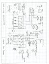
Wiring patterns were drafted for the ignition system, turn signals, and panel. (The ignition system was previously temporarily wired so the engine could be test started).


Comments on the wiring design:
1. Multiple relays were used so no high current loads would pass through the panel switches. Exceptions are the head light wires coming from the DIP switch and the turn signal wires coming from the Lucas pneumatic switch, both of which are high current devices.
2. The turn signals / four-way flashers required three relays and a separate flasher unit. (There may be easier ways to accomplish this with prefabricated units.) The flasher module is designed to work with LED lights as well as standard filament bults in case we chose to use LEDs, such as for the tail and brake lights.
3. The power source from the battery to the panel runs through a 50-amp fuse. The large black volage regulator to the right of the fuse boxes is essentially a non-functional replica, but it does include a 50-amp fuse which was utilized in the wiring. (Although we have an original type silver colored voltage regulator as per the original, we opted for the reproduction because we prefer the black color and the internal fifty-amp fuse – a deviation from the original look).


4. The top panel switch is for the fuel pump so that it can be turned off to the drain the carbs before the ignition is turned off. The fuel pump has its own fuse and breaker to assure it will continue to function in the event another device’s breaker or fuse blows.
5. The bottom panel switch turns the radiator fan on and off. We opted not to incorporate a thermostatic switch at this time, although it could be added later if necessary. Although the original had only three switches on the left side, the fourth actually better balances the look; another deviation from the original.
5. Lucas components were used for all the switches, fuse boxes, and ignition components, as itemized in a prior post.
More details to some.
Wiring patterns were drafted for the ignition system, turn signals, and panel. (The ignition system was previously temporarily wired so the engine could be test started).
Comments on the wiring design:
1. Multiple relays were used so no high current loads would pass through the panel switches. Exceptions are the head light wires coming from the DIP switch and the turn signal wires coming from the Lucas pneumatic switch, both of which are high current devices.
2. The turn signals / four-way flashers required three relays and a separate flasher unit. (There may be easier ways to accomplish this with prefabricated units.) The flasher module is designed to work with LED lights as well as standard filament bults in case we chose to use LEDs, such as for the tail and brake lights.
3. The power source from the battery to the panel runs through a 50-amp fuse. The large black volage regulator to the right of the fuse boxes is essentially a non-functional replica, but it does include a 50-amp fuse which was utilized in the wiring. (Although we have an original type silver colored voltage regulator as per the original, we opted for the reproduction because we prefer the black color and the internal fifty-amp fuse – a deviation from the original look).
4. The top panel switch is for the fuel pump so that it can be turned off to the drain the carbs before the ignition is turned off. The fuel pump has its own fuse and breaker to assure it will continue to function in the event another device’s breaker or fuse blows.
5. The bottom panel switch turns the radiator fan on and off. We opted not to incorporate a thermostatic switch at this time, although it could be added later if necessary. Although the original had only three switches on the left side, the fourth actually better balances the look; another deviation from the original.
5. Lucas components were used for all the switches, fuse boxes, and ignition components, as itemized in a prior post.
More details to some.
Attachments
Last edited: