The NRG looks nice and clean. I like it.

- Forums
- GT40 Replica Manufacturers' Corner
- RCR Forum - RCR40/SLC/917/Superlite Aero
- The SLC Clubhouse
You are using an out of date browser. It may not display this or other websites correctly.
You should upgrade or use an alternative browser.
You should upgrade or use an alternative browser.
Dan's Build
- Thread starter Dan carter
- Start date
If anyone is interested, the steering wheel is the MOMO Tomcat.
Day 157
<?xml:namespace prefix = "o" ns = "urn:schemas-microsoft-com<img src=" /><o ></o>The AC system is kicking my posterior. Perhaps I am being a tad bit anal about the install, so it’s taking way longer than I want. Getting from the compressor up the sides to the bulkhead hasn’t been too bad, but once inside the firewall, installing the evaporator and getting both coolant lines and two heater lines into that confined space has proven to be the toughest challenge yet. The final configuration is not complete, but below are a couple of pictures of solutions I hope are the answers, just not yet proven.<o></o>
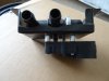
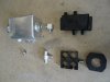
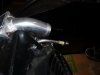
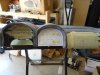
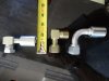
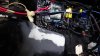
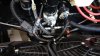
To plumb out the engine coolant flow, I have elected to run a “burp” line from the radiator and the engine steam port to the top of the Canton reservoir. I was finally able to find a SS tee fitting that supported two ¼ lines. The bottom of the Canton will feed the engine and the 4 way coolant diverter valve needed for the LS engine. As you can see I built a mounting bracket for that diverter valve which will mount near the engine (still undecided). I only needed a ¾ x 5/8 x ¾ tee to link the diverter valve and the engine coolant return lines, so the hose connections were very basic. <o></o>
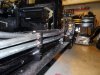
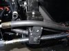
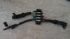
I made some tubing holders to go down the side of the car as shown. If anyone is interested, I can get you in touch with the machine shop that made them.
<o></o>
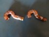
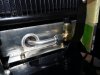
Since Vintage Air decided to locate all four line inputs on the bulkhead side of the evaporator, the challenge is to create enough separation in the lines to get proper fitment. I have not yet completed the install, but I sweated some copper pipe into the question marks in the pictures to create an immediate reward turn of the heater hoses to create space and separation of the coolant lines and the heater lines. I think this will solve one problem. The exit points thru the bulkhead are key as both the body and the interior tub need to be considered for space. More to come on this hopefully this week (it’s my goal to complete it anyway).<o></o>
<?xml:namespace prefix = "o" ns = "urn:schemas-microsoft-com<img src=" /><o
></o>The AC system is kicking my posterior. Perhaps I am being a tad bit anal about the install, so it’s taking way longer than I want. Getting from the compressor up the sides to the bulkhead hasn’t been too bad, but once inside the firewall, installing the evaporator and getting both coolant lines and two heater lines into that confined space has proven to be the toughest challenge yet. The final configuration is not complete, but below are a couple of pictures of solutions I hope are the answers, just not yet proven.<o></o>To plumb out the engine coolant flow, I have elected to run a “burp” line from the radiator and the engine steam port to the top of the Canton reservoir. I was finally able to find a SS tee fitting that supported two ¼ lines. The bottom of the Canton will feed the engine and the 4 way coolant diverter valve needed for the LS engine. As you can see I built a mounting bracket for that diverter valve which will mount near the engine (still undecided). I only needed a ¾ x 5/8 x ¾ tee to link the diverter valve and the engine coolant return lines, so the hose connections were very basic. <o
></o>I made some tubing holders to go down the side of the car as shown. If anyone is interested, I can get you in touch with the machine shop that made them.
<o
></o>Since Vintage Air decided to locate all four line inputs on the bulkhead side of the evaporator, the challenge is to create enough separation in the lines to get proper fitment. I have not yet completed the install, but I sweated some copper pipe into the question marks in the pictures to create an immediate reward turn of the heater hoses to create space and separation of the coolant lines and the heater lines. I think this will solve one problem. The exit points thru the bulkhead are key as both the body and the interior tub need to be considered for space. More to come on this hopefully this week (it’s my goal to complete it anyway).<o
></o>Attachments
Day 179
<?xml:namespace prefix = "o" ns = "urn:schemas-microsoft-com
 The AC plumbing continues to be a major challenge. In trying to sweat the copper tubing on to the Vintage Air box, I had a minor heat problem and had to re-order a new box. It would have been very useful if Vintage was able to send the unit in such a way that the plastic box would come off, but they use some type of melted super glue and they were not willing to ship it that way. So I will make a better decision with box two…..lesson learned.
<o></o>
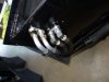
1. Picture four: This is how I ran the heater and coolant lines from the engine, around the corner and down the sides. Brackets were made to accommodate the coolant diverter valve (needed for the LS engine).
<o></o>
2. I bent coolant tubing to run from the condenser thru the radiator holes and will attach the rubber coolant lines on the other side of the radiator. I found running the rubber tubes thru the radiator was not going to be easy and the constant focused heat on any rubber in that radiator hole was an item of concern anyway.
<o></o>
3. Once the new evap box arrives, I will seek the wisdom of a radiator shop this time to help me solve the plumbing problem. :furious:<o></o>
</P>
<?xml:namespace prefix = "o" ns = "urn:schemas-microsoft-com
<o
></o>1. Picture four: This is how I ran the heater and coolant lines from the engine, around the corner and down the sides. Brackets were made to accommodate the coolant diverter valve (needed for the LS engine).
<o
></o>2. I bent coolant tubing to run from the condenser thru the radiator holes and will attach the rubber coolant lines on the other side of the radiator. I found running the rubber tubes thru the radiator was not going to be easy and the constant focused heat on any rubber in that radiator hole was an item of concern anyway.
<o
></o>3. Once the new evap box arrives, I will seek the wisdom of a radiator shop this time to help me solve the plumbing problem. :furious:<o
></o></P>
Attachments
Dan,
Is your setup atypical? Why are you having to invent so much in the way of plumbing and mounting? I'm not questioning your decisions as much as I am trying to decipher the challenges involved.
According to the Superlite website, they include what's required for the installation:
STAGE 13 – AIR CONDITIONING $1,895
Air conditioner and heater. This powerful and compact unit keeps the occupants cool or warm, no matter the outside temp. Specifically engineered for the SLC, this unit includes the compressor, condenser, drier, super efficient and compact evaporator, a trinary switch and rotating, closing dash outlets designed for the standard dash. Provided with hard and soft lines and hose ends. A professional AC shop will normally be required to charge the system.
-AC Compressor Mounting Bracket
-AC Fiberglass dash manifold
-AC evaporator mount and duct system
Day 194
<?xml:namespace prefix = "o" ns = "urn:schemas-microsoft-com<img src=" /><o></o>
For what it’s worth, I am now referring to my SLC as a Component Race Car, being hand crafted to be street legal. It is not a kit car (seems to avoid any kit car stigma).<o></o>
<o></o>
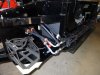
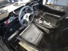
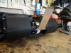
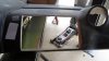
1. Ok a few things going on. I mounted both the shifter and e-brake as shown. <o></o>
2. The tub was cut to accommodate the mounting of the shifter. Discovered the shifter is 3 inches wide, the tub only two….something had to give.<o></o>
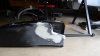
3. Made a decision on how to route the lines for the heater/cooling. As shown in the picture, there are several choices to make hard turns with the plumbing if you choose to go thru the firewall anywhere. I found the tub and the main body dimensions must be considered when you decide where to drill holes and route tubing thru the firewall….exercise caution, measure twice drill once. Glad to say I got it right the first time…..not without a lot of sweat however. I found the shortest turn in parts from Cold Hose as shown. Worked great for me.<o></o>
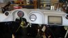
4. I want to augment the KOSO gauge with a quad gauge mounted in the center pod on the dash board. I am going to try the Alpine ILX-007 stereo as discussed in another blog, mounting on the passenger dash side by modifying the dash some to accommodate the fit.<o></o>
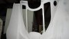
5. I made a mold to cover the Graz hole in the tail section and will glass that in soon.<o></o>
<?xml:namespace prefix = "o" ns = "urn:schemas-microsoft-com<img src=" /><o
></o>For what it’s worth, I am now referring to my SLC as a Component Race Car, being hand crafted to be street legal. It is not a kit car (seems to avoid any kit car stigma).<o
></o><o
></o>1. Ok a few things going on. I mounted both the shifter and e-brake as shown. <o
></o>2. The tub was cut to accommodate the mounting of the shifter. Discovered the shifter is 3 inches wide, the tub only two….something had to give.<o
></o>3. Made a decision on how to route the lines for the heater/cooling. As shown in the picture, there are several choices to make hard turns with the plumbing if you choose to go thru the firewall anywhere. I found the tub and the main body dimensions must be considered when you decide where to drill holes and route tubing thru the firewall….exercise caution, measure twice drill once. Glad to say I got it right the first time…..not without a lot of sweat however. I found the shortest turn in parts from Cold Hose as shown. Worked great for me.<o
></o>4. I want to augment the KOSO gauge with a quad gauge mounted in the center pod on the dash board. I am going to try the Alpine ILX-007 stereo as discussed in another blog, mounting on the passenger dash side by modifying the dash some to accommodate the fit.<o
></o>5. I made a mold to cover the Graz hole in the tail section and will glass that in soon.<o
></o>Attachments
Looking good- AC lines are neat!
Day 272
Well even the best made plans exceed their time limits. Thought I would be completed by now, silly me. I've been monitoring everyone else in their builds, so here is my status...nothing exciting.
A few things to report. I have been bouncing back and forth between wiring, finishing the coolant plumbing (finally), body work, and tail light redo. So for those builds in progress here are a few items you may find useful:
<?xml:namespace prefix = "o" ns = "urn:schemas-microsoft-com<img src=" /><o></o>
1. If you’re using the Bosch SLC starter and are searching for the harness connector that mates to the square spade plug, try the following Volkswagen parts:1J0-972-743 (seal), 357-972-771 (housing), and 000-979-227-E (wire).Makes a nice weather tight plug connector that mates to the Bosch.
<o></o>
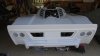
2. Modified the tail section to cover the hole created by the Graziano so it’s covered.
<o></o>
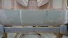
3. Prototyped a system to integrate a wing into the Street tail (more to come with additional testing)
<o></o>
4. Modified the SLC taillight fiberglass part to accommodate round LED taillights. IAW Infinity, their system will accommodate LED lights without any concern over signal strength to activate blinkers. The LED being used is an all-inclusive unit…simple: brake light, backup light, driving light, and turn signal.Found the harness connector for the backup switch on the Graz for a nice clean install. Work still in progress but you can see the direction its going.
<o></o>
5. Carefully working the interior tub install.Since the tub will not go into the car with the roll bar on (don’t plan to cut it into two…..but maybe), sequencing the steps and layout of wiring harnesses etc needs careful planning to minimize taking it in and out multiple times (gee wonder how I know that…LOL).
<o></o>
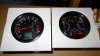
6. Decided to go another direction with the instrument cluster.I like needles and dials so going with a SpeedHut layout. They allow you to customize your system and the price is very reasonable. These are their 4 inch gauges which will fit nicely. Sorry, but the quad is upside down.<o></o>
Well even the best made plans exceed their time limits. Thought I would be completed by now, silly me. I've been monitoring everyone else in their builds, so here is my status...nothing exciting.
A few things to report. I have been bouncing back and forth between wiring, finishing the coolant plumbing (finally), body work, and tail light redo. So for those builds in progress here are a few items you may find useful:
<?xml:namespace prefix = "o" ns = "urn:schemas-microsoft-com<img src=" /><o
></o>1. If you’re using the Bosch SLC starter and are searching for the harness connector that mates to the square spade plug, try the following Volkswagen parts:1J0-972-743 (seal), 357-972-771 (housing), and 000-979-227-E (wire).Makes a nice weather tight plug connector that mates to the Bosch.
<o
></o>2. Modified the tail section to cover the hole created by the Graziano so it’s covered.
<o
></o>3. Prototyped a system to integrate a wing into the Street tail (more to come with additional testing)
<o
></o>4. Modified the SLC taillight fiberglass part to accommodate round LED taillights. IAW Infinity, their system will accommodate LED lights without any concern over signal strength to activate blinkers. The LED being used is an all-inclusive unit…simple: brake light, backup light, driving light, and turn signal.Found the harness connector for the backup switch on the Graz for a nice clean install. Work still in progress but you can see the direction its going.
<o
></o>5. Carefully working the interior tub install.Since the tub will not go into the car with the roll bar on (don’t plan to cut it into two…..but maybe), sequencing the steps and layout of wiring harnesses etc needs careful planning to minimize taking it in and out multiple times (gee wonder how I know that…LOL).
<o
></o>6. Decided to go another direction with the instrument cluster.I like needles and dials so going with a SpeedHut layout. They allow you to customize your system and the price is very reasonable. These are their 4 inch gauges which will fit nicely. Sorry, but the quad is upside down.<o
></o>Attachments

Day 297
<?xml:namespace prefix = "o" ns = "urn:schemas-microsoft-com<img src=" /><o></o>
1. Housing for the 4 LED tail lights completed. The cutout for the rear window vents were reinforced with ½ round to stiffen up the area for the window and movement of bonnet. Thanks to Mike, a prototype mounting system is in work to mount a wing onto the street tail that is connected to the chassis. The wing will rotate with the tail so no removal is necessary. The tail was modified to cover the Graziano unit.
<o></o>
2. Front wiring completed wrapped in fire resistant Marine grade loom.Front wiring harness modified to allow for windshield washer system. <o></o>
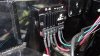
3. Since I am using the Aeromotive fuel systems, I elected to use the fuel pump controller for the high pressure pump. This controller in addition to the Speedhut tach can both use the tach signal from the ECU, but require differing boosted power to operate. So, one tach wire, one ignition power source, two resistors and two outputs required development of a simple connection board to accommodate the needed signals. Used a 4 way bus board get a clean install (see picture). <o></o>
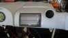
4. Using the Alpine ILX-007 radio system.Dash in modification to allow install.Using a Pioneer universal mount kit with some glass work to fit the system into the dash. Will use an Alpine rear view camera with a backup by Pass switch to allow for constant rear view at the drivers discretion.
<o></o>
5. Both the fiberglass tub and console got some glass work to fit around my Infinity Powerbox and AC installs respectively.Built a rear bracket for the AC system to hold up the weight from the rear of the unit.
<o></o>
6. As for switches, found a company called Rocker Switch Pros that will laser etch rocker switches to any configuration you want.Going to try them out in addition to other recommendations for the dash system<o></o>
<?xml:namespace prefix = "o" ns = "urn:schemas-microsoft-com<img src=" /><o
></o>1. Housing for the 4 LED tail lights completed. The cutout for the rear window vents were reinforced with ½ round to stiffen up the area for the window and movement of bonnet. Thanks to Mike, a prototype mounting system is in work to mount a wing onto the street tail that is connected to the chassis. The wing will rotate with the tail so no removal is necessary. The tail was modified to cover the Graziano unit.
<o
></o>2. Front wiring completed wrapped in fire resistant Marine grade loom.Front wiring harness modified to allow for windshield washer system. <o
></o>3. Since I am using the Aeromotive fuel systems, I elected to use the fuel pump controller for the high pressure pump. This controller in addition to the Speedhut tach can both use the tach signal from the ECU, but require differing boosted power to operate. So, one tach wire, one ignition power source, two resistors and two outputs required development of a simple connection board to accommodate the needed signals. Used a 4 way bus board get a clean install (see picture). <o
></o>4. Using the Alpine ILX-007 radio system.Dash in modification to allow install.Using a Pioneer universal mount kit with some glass work to fit the system into the dash. Will use an Alpine rear view camera with a backup by Pass switch to allow for constant rear view at the drivers discretion.
<o
></o>5. Both the fiberglass tub and console got some glass work to fit around my Infinity Powerbox and AC installs respectively.Built a rear bracket for the AC system to hold up the weight from the rear of the unit.
<o
></o>6. As for switches, found a company called Rocker Switch Pros that will laser etch rocker switches to any configuration you want.Going to try them out in addition to other recommendations for the dash system<o
></o>Attachments
-
 DSC02530.jpg120.4 KB · Views: 492
 -
 DSC02552.jpg236.3 KB · Views: 469
 -
 DSC02554.jpg144 KB · Views: 449
 -
 AC wiring with Infinity.jpg49 KB · Views: 513
 -
 DSC02382.JPG169.5 KB · Views: 485
 -
 DSC02526.jpg230.7 KB · Views: 487
 -
 DSC02548.jpg211.9 KB · Views: 492
 -
 DSC02533.jpg145.6 KB · Views: 444
 -
 DSC02551.jpg135.7 KB · Views: 478
I used a similar company to make custom actuator covers for the Carling switches in my car. Very cool, and very custom.
Attached find pictures of my approach to installing the Alpine ILX-007 into my dash. I used the Pioneer universal mounting system which fit perfectly and did some glass work to modify the dash. Gauges are in for test fit, switches are next.
Attachments
Looking great Dan! Really clean install on the Alpine! Have you tried reaching for the controls while strapped into the seat? I have short arms and I've definitely got concerns about being able to reach for anything on the passenger side when strapped in.
Are you planning to run a harness or a system that incorporates a ratcheting mechanism?
Are you planning to run a harness or a system that incorporates a ratcheting mechanism?
Cam
I did do a stretch test, and yes it is a bit of a reach, but I have a really long wing span....I'm 6'2. I will be using a harness, but this system will work from my iPhone which can act like a remote. I am adding a switch to activate the secondary video to be my rear view mirror. While perhaps not the optimal location for viewing continuously it will improve situational awareness.
I did do a stretch test, and yes it is a bit of a reach, but I have a really long wing span....I'm 6'2. I will be using a harness, but this system will work from my iPhone which can act like a remote. I am adding a switch to activate the secondary video to be my rear view mirror. While perhaps not the optimal location for viewing continuously it will improve situational awareness.
Day 312
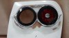
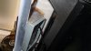
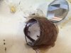
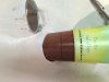
With so many solutions out there I thought I was off to the races on the headlights and ran into a small problem, literally. My two lenses are both 90MM in width, the nose cone holes in are not. So option one was to sand away…..not enough width in the mold to do that. Option two was to mold in a bigger whole. Now to craft a mold of some type that was 90MM round……plastic drinking cups worked well. As you can see from the picture, I sliced out a lot of the headlight tunnel, inserted the main cup up to the 90MM width point. The second cup is to assist in maintaining the cylinder shape.I would recommend pure white cups, as the print came off and stuck to the glass. It will sand off easy enough anyway. I will work the glass on Monday to complete the lens installs.
<?xml:namespace prefix = "o" ns = "urn:schemas-microsoft-com<img src=" /><o></o>
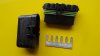
Found a product that perhaps many of you know about already, but take a look at the picture. Ran across a simple and clean way to share a signal, or voltage with several wires without crimping them altogether or something similar. This connector from Waytech really simplified some wiring issues I was having. Connect your source to one end of the spade common bar along with the wires you want to share, install in the connector and snap on the cover and you have a quick and easy bus bar. Of course watch the amount of AMPs you load up on that circuit. Just sharing.
<o>Has anyone tried to replace the headlight bulbs with LED bulbs?</o>
With so many solutions out there I thought I was off to the races on the headlights and ran into a small problem, literally. My two lenses are both 90MM in width, the nose cone holes in are not. So option one was to sand away…..not enough width in the mold to do that. Option two was to mold in a bigger whole. Now to craft a mold of some type that was 90MM round……plastic drinking cups worked well. As you can see from the picture, I sliced out a lot of the headlight tunnel, inserted the main cup up to the 90MM width point. The second cup is to assist in maintaining the cylinder shape.I would recommend pure white cups, as the print came off and stuck to the glass. It will sand off easy enough anyway. I will work the glass on Monday to complete the lens installs.
<?xml:namespace prefix = "o" ns = "urn:schemas-microsoft-com<img src=" /><o
></o>Found a product that perhaps many of you know about already, but take a look at the picture. Ran across a simple and clean way to share a signal, or voltage with several wires without crimping them altogether or something similar. This connector from Waytech really simplified some wiring issues I was having. Connect your source to one end of the spade common bar along with the wires you want to share, install in the connector and snap on the cover and you have a quick and easy bus bar. Of course watch the amount of AMPs you load up on that circuit. Just sharing.
<o
>Has anyone tried to replace the headlight bulbs with LED bulbs?</o>Attachments
Looks good Dan. I would try to get reviews on any led headlight, or bulb, you were thinking of first. Some are just garbage, and some are only good enough for a normal street car. You run a good possibility to out drive your headlights in an SLC, so anything less than stellar light output won't cut it.
I installed 55watt hid bulbs/ballasts in both my main and high beams, but with both 60mm housings, not the original 90mm. The 60mm seem to have a much higher output, and with 55watt ballasts, I can blind someone on the moon!
I did 6000k temp on my main beams, and 4000k on the highs.
I installed 55watt hid bulbs/ballasts in both my main and high beams, but with both 60mm housings, not the original 90mm. The 60mm seem to have a much higher output, and with 55watt ballasts, I can blind someone on the moon!
I did 6000k temp on my main beams, and 4000k on the highs.
Dan - I would highly recommend that you NOT use LED bulbs in place of your driving light bulbs. These ligh housings are designed around a specific bulb type. Every bulb produces light at a specific point within the glass element. All the contours within the housing assembly are such that they expect light at this point - the focal point. Using a different bulb will produce light at a different location within the housing. This causes the light rays to travel in directions not originally intended - which creates glare and poor light focus.
Regarding HID conversions, I'm dubious that HID bulbs produce light at the same focal point as the halogen bulb they're standing in for (I'm talking about the ones converted into standard halogen based units sold in the aftermarket). If you're going HID be sure to use a housing designed for HID, or make whatever alterations are necessary to line your HID bulb up with the intended focal point within the light housing assembly. Otherwise you may get people flashing their high beams at you because they think you're running your brights.
Regarding HID conversions, I'm dubious that HID bulbs produce light at the same focal point as the halogen bulb they're standing in for (I'm talking about the ones converted into standard halogen based units sold in the aftermarket). If you're going HID be sure to use a housing designed for HID, or make whatever alterations are necessary to line your HID bulb up with the intended focal point within the light housing assembly. Otherwise you may get people flashing their high beams at you because they think you're running your brights.
Good data to have. Thanks gents.
The proof will be in pudding, once I get them turned on.
The proof will be in pudding, once I get them turned on.
I have tested both the Hella 90mm housings, and 60mm housings with the 55watt. Let sit on for two hours in garage with zero airflow, and they were still fine. The Hella ones are built well enough to handle the extra heat. The 35watt would create even less heat.
The cut off line with each size Hella is very crisp on your driving lights. As long as you have them aimed correctly, you will be fine.
With what I am running for lights, It really has the output and safety of a new high end car.
The cut off line with each size Hella is very crisp on your driving lights. As long as you have them aimed correctly, you will be fine.
With what I am running for lights, It really has the output and safety of a new high end car.
Scott
Let me ask you this. Trying hard to keep the "top" as marked facing up after removing one of the four mounting tabs. How sensitive are the lights to that positioning, aka is the beam internally shielded or directed?
Must be a reason Hella marks the top.
Let me ask you this. Trying hard to keep the "top" as marked facing up after removing one of the four mounting tabs. How sensitive are the lights to that positioning, aka is the beam internally shielded or directed?
Must be a reason Hella marks the top.
Ken Roberts
Supporter
The beam has a cutoff pattern to it. It is imperative that the top mark is at the 12 oclock position. If you were to drive up to a wall at night and look at the pattern produced on the wall you'd see a distinct upper cutoff pattern that is horizontal to the ground. Here is a video that shows the cutoff on a garage door.
https://www.youtube.com/watch?v=03fHzDEHVV4
https://www.youtube.com/watch?v=03fHzDEHVV4
Similar threads
- Replies
- 14
- Views
- 5K