Dan's Build

Ya, Ken got it answered already. Luckily you asked, you would have been one unhappy camper to get all your adjusters in to turn on, and have in a bad rotation. Lol.
 
Day 380

Well, I’m well over schedule now, so I have tossed the schedule. Someone advised me I would be done on Friday, I just don’t know which Friday….so we move on.
<?xml:namespace prefix = "o" ns = "urn:schemas-microsoft-com<img src=" /><o:p></o:p>
1. Wires, wires and more wires.I decided to change the instrumentation to a system with dials and gauges (just because I’m not a digital gauge guy). In doing so, I ended up with a triage of connectors and wires that looked like the space shuttle. So I have rewired and re-bundled the cockpit with Delphi GT 150 and GT 280 connectors dependent on amperage. It is taking some time, lots of drawings and diagrams to keep from getting lost, and trying to produce a very clean layout.I’ve included a sample of the wire connectors and a picture of the dash in progress.
<o:p></o:p>
2. I had my toggle switches custom made and the prices were very reasonable. They will light up with dash lights, and also light brighter when the switch is activated.
<o:p></o:p>
3. I pulsed the blog about what folks did with the splitter support. When using the fender well kit, the support creates an install problem. The brace can me moved to be inside the wheel well next to the tire, but I went inside the wheel well.I don’t see any current issue in doing so and especially since I am not going to hinge the front rather lift it straight up. You can see in the picture the approach I took.I hope it works.I also discovered that I will need to utilize a quick disconnect for the wires going to the head lights. They are rather high amperage so my current plan is to use trailer light connectors in some cleaver way to act as the quick disconnect when I want to remove the nose.
<o:p></o:p>
4. I vacillated on how to finish the headlights.In the end I went ahead and mounted the standard 90MM Hella lights, but may on some future date opt to integrate an OEM headlight system into the car. While I got them in, I am not completely satisfied with the result, but they will be functional.
<o:p></o:p>
5. Working the air intake system and plan on opening up the rear scoops to feed fresh air to the breather system. More on that later.<o:p></o:p>
 

Attachments

  • DSC02663.jpg
    DSC02663.jpg
    112.3 KB · Views: 455
  • DSC02643.jpg
    DSC02643.jpg
    163.5 KB · Views: 539
  • DSC02666.jpg
    DSC02666.jpg
    179 KB · Views: 496
the way you slotted it makes it seem like it would be a pain in the ass to get off - i'd remove the area behind the slot to make it easier to go off/on
 

Ken Roberts

Supporter
Are you keeping the dash white Dan? Almost all production cars have black on the top portion of the dash. This is to prevent seeing the reflection in the windshield. It could be bothersome.

I just realized that it's most likely a white primer for now.
 
Last edited:
Ken

Nah that is just primer. I will have my painter integrate the outside color with his special carbon look technique with black. I'm going to try the soft touch finish on it to see how that looks.
 
Day 398

I have spent a long time on the wiring, despite the having the Infinity System. The change up in dash instruments and running a separate ground system via a bus network has consumed a lot of stringing and wire. <?xml:namespace prefix = "o" ns = "urn:schemas-microsoft-com<img src=" /><o:p></o:p>

1. Finished the battery install and believe I have left enough room for the fender wells based on the rear wheel position.
<o:p></o:p>
2. The dash wiring is completed and as you can see the use of the small bus bar system from Waytech came in very handy. It allowed be to tap into either an ignition hot source or constant power source within AMP limits.
<o:p></o:p>
3. For those who may not have read the separate discussion on the QA1 shocks and the lift puck, the bottom line is it didn’t matter on the orientation of the shock or the lift puck, so I have mounted mine “upside down”. As mentioned in that specific string, the spring down orientation does aid in changing the springs if you need too, and reduces the un-sprung weight for the serious racer.For the rest of us it really won’t matter much.
<o:p></o:p>
4. I started on the air induction and will pretty much imitate the Mike’s install. I do plan on building a box and integrating the rear scoops. I will be giving some thought to minimizing any water that enters and diverting it away from a direct shot at the filter. <o:p></o:p>
 

Attachments

  • DSC02674.jpg
    DSC02674.jpg
    224 KB · Views: 395
  • DSC02690.jpg
    DSC02690.jpg
    183 KB · Views: 431
  • DSC02688.jpg
    DSC02688.jpg
    229.3 KB · Views: 432
  • DSC02670.jpg
    DSC02670.jpg
    169 KB · Views: 429
  • DSC02682.jpg
    DSC02682.jpg
    224.9 KB · Views: 413
Alex

It's not that hard to remove, lifts straight off. I will actually need both areas either side of the slots to mount the inner fender wells if I understand your comment correctly.
 
Thanks Scott

Glad the wiring is nearly over....I will power it up after Christmas. Don't want any electrical faux pas hanging over my head until next week....ha.
 
Day 400

A quick update on the quick disconnect plan. After many priced the crimper (~$400) and went with the most simpe solution, an RV plug. Each plug accommodates 7 wires which is perfect for the headlight system.

Recall I moved the splitter brace inside the soon to be installed fender well and slotted the hood to accommodate lifting is straight up and off. What is not in the picture is the male part of the harness which will connect to the headlights themselves. There will enough slack in the line to allow for lifting a side, reach in and unplugging ghe connector. A bit tedious but not an area that will be accessed frequently anyway.

I plan to build a duct from the front scoop along the splitter and release air to the front brakes. Actually using a rain gutter as a template for the glass tube under construction.
 

Attachments

  • DSC02693.jpg
    DSC02693.jpg
    144.3 KB · Views: 409
Day 412

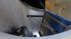
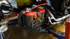
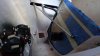
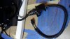
A major milestone today. All the non-engine electrical circuits were checked and few wires that I swapped were corrected. The nose headlight quick disconnect is pictured below and finished. The use of a simple trailer hitch plug works.

1. If you plan on using the Alpine ILX 007, here is a discovery. I hooked an Alpine rear view camera to the license plate holder and found that the radio has a hand brake trip signal. The radio will not allow you to access certain functions until this wire is grounded. If you go to the Alpine web, you can download the owners manual. Item 17 page 30 identifies this wire as the Parking Brake lead (Yellow/Blue). To make this work so you can access the setup menu, simply turn on the radio and ground this wire. You will have access to the setup menu. I plan to connect this to a small button to act as the parking brake trigger, its a simple ground.

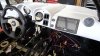
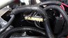
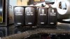
2. I customized some cockpit switches as shown. They light up with the parking lights, and have an indicator that the switch is on. I doubled up on a couple of functions to save space (aka on-off-on). As you can see, one switch is labeled "camera". That is my rear view function in lieu of a rear view mirror. I hit the switch and I have instant rear view camera. Turn it off and back to radio. The 4 way flashers are on the down side of that same switch. The other double switch is an experiment. One temperature gauge that toggles between engine and transmission temperature....not sure if or how it will work yet. Have to figure out the temperature sensor on the Graz.
 

Attachments

  • DSC02761.jpg
    DSC02761.jpg
    186.3 KB · Views: 329
  • DSC02760.jpg
    DSC02760.jpg
    124.3 KB · Views: 317
  • DSC02764.jpg
    DSC02764.jpg
    165.2 KB · Views: 395
How were you able to label the rocker switches?

Don't forget to heat shrink the white wire too. lol. that type of heatshrink is killer for auto work. Tough as nails.
 
Back
Top