Dan's Build

:thumbsup:

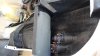
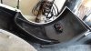
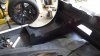
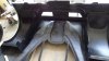
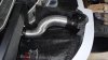
Now off to make the two front lower A arms square to the cars track and frame.

By adjusting the lower heims in or out, it will cause the outside of the A arm to pivot in an arc. The goal is to make both lower A arms the same distance fore and aft from vehicle center line. This movement I presume impacts Caster some, so that measure can be adjusted with the upper A arm spacers.

Found a really good article from LongAcre on how to square a race car that does not require a plumb bob. I googled "how to square your race car" and it came up. Going to try their technique as it seems less prone to measuring errors.

Great discussion. Thanks
 
While we are on the subject of getting the suspension square, are people measuring track using the centerline of the wheel/tire, or the outermost edge of the wheel/tire? I'm hoping to do my initial suspension assembly soon and was planning to use the wheel centerlines; so if matching track front to rear that means the rear wheels will actually stick slightly outboard in comparison.

Edit: in dan's description above it looks like he is planning to use lower ball joints but I'm not sure I can get a good measurement using the balljoints. The pins move and it's difficult to establish the center point. My front ball joints don't have zerk fittings so no convenient center on the bottom of those.
 
Cam

I'm going to use a stationary point on the A arms that are identical on both sides. I sent you the LongAcre racing link on how to square your race car. It describes a method that seems more accurate, is easily repeated and is portable if needed. Take a look. I'm trying it now and so far it's so much easier than the old plumb bob method.

Have fun, this is tedious. I was informed by a racer, that they use 1/8 inch as the max tolerance, but I think it's possible to get closer with this optional approach. I will see.
 
the longacre method sets the wheels so the outside edges are aligned front to back. Will this method set the rear wheels so they are aligned with the rear wheel wells, or will this push them inboard an inch?
 
Cam

I'm going to modify the approach a bit by using the technique without tire on. I want to ensure the suspension is square to the frame and I think this technique will be easier than plumb bobbing. Haven't tried it just yet but I can't see why it won't give better readings than transferring bob points to the floor.

I will just have to see.
 
Last edited:
Let me explain the differences in my measurements. I went to the ball joint centerline, and did this measuring shortly after I bought the car. So, I was double checking someone elses work on the squaring set up and suspension install. It was off. This does not mean the frame mounting points are off, as I wasn't checking that. Being 1/2 turn off on the rod end depth could control an 1/8" movement out at the ball joint. So, my measurements say 1/8"+ on one side, and 1/8"- on the other, that will get the car lowers square based on current rod end depth.
In other words, I will be redoing it from the start of the process and see where that 1/8" is hiding. My guess is rod end depth, and not difference in chassis mounting points.

There is plenty of adjustment to get the car perfect.
 
Tried the Longacre method to square the car with plumb bobbing as my backup. The car was off square close to 1/2 inch. It took very few turns on the heim joints to square it up but I really thought the long acre technique was easy and effective. The suspension is now square to less the 1/16 of an inch. And that is most likely the margin of error in reading the tape measure all morning.

Thanks Scott for the heads up on this subject.
 
Funny you should say that Scott because I drove the car without body today for the first time. Car bucks some but GPS vas was not hooked up (oops).

Have adjust reverse cable, could not find it.....but only went forward anyway. Neighbors are going to hate this car.....ha

:laugh:
 
As a follow-up to the Longacre article on squaring your race car, I took the car to a professional alignment shop today to confirm my measures.

Nothing was out of tolerance enough to attempt to reset any of the caster, toe or camber readings. This validated for me the simplicity and repeatability of the method described in the article from Longacre. I recommend it to anyone looking for a good do it your self article.

longacreracing.com/userfiles/articles/text/Squaring.pdf
 
Day 542
<?xml:namespace prefix = "o" ns = "urn:schemas-microsoft-com<img src=" /><o:p></o:p>
1. Read with extreme interest the discussion (John Burer’s thread) on the Graz gearing and its impact on the car mated to an LS3/480. I think it goes without question the OEM gears are not the best for the HP/Torque specs of the LS engine. Based on the chart pictured below, I made a choice on which transfer gear set to change to. There seems to be a 70/30 split on the 1.038 set versus the .76 gears. I found and built my own RPM vs Speed tables based on the engineering formulas included in the picture and used my C6 Corvette Z-51 gears and speed as my baseline. While the 1.038 gears set imitates the Corvette best gears 1-4, the tipping point for me was the cruising RPM at interstate speeds………at 80, the Corvette RPM is 2000. With the .76 the SLC it will be ~1800, and with the 1.038 ~2500. The Vette weighs in at nearly 3400 lbs with an LS2 (400hp/400 ft lbs). I expect the SLC to be around 2700-2800 lbs when finished with 480 HP and 480 ft lbs. I am not building a dedicated track car (too expensive if I wreck it), so this is a street cruiser. I know some builders have already tried the .76 gears and are not impressed with the acceleration, so I hope my choice doesn’t prove to be a disappointing decision.
<o:p></o:p>
2. Finished integrating a set of cold air induction scoops off the street tail to the main engine filters. I am experimenting on a way to prevent water from getting to the main filter and so far the technique shows some promise.
<o:p></o:p>
3. Cut access ports into the aluminum plate behind the seats to allow access to my fuel system and the fuel level indicators. If you are using the RCR interior tub, if you don’t create an access door, the entire body and tub have to be removed to gain easy access. <o:p></o:p>

4. Coating the back side of the fiberglass with a two-part bed liner that is thinner than most truck liners. It adds some sound protection and a barrier to help protect the fiberglass.<o:p></o:p>

5. Struggling a bit to get the tail section to align squarely with the main body. When measuring the main body from the center of the wheel well arc front to back along a horizontal line, I noted the length on one side is bigger than the other. Not sure why, but I will keep working the mating until I get mating gaps that are acceptable on both sides.

6. Built speaker platforms into the tub and not the doors to mount my JBL speakers. Not planning for a premium sound system, so they are relatively small.<o:p></o:p>


<o:p></o:p>
 

Attachments

  • Gear vs Speed Charts.jpg
    Gear vs Speed Charts.jpg
    232.5 KB · Views: 418
  • IMG_1320.JPG
    IMG_1320.JPG
    113.4 KB · Views: 490
  • IMG_1329.JPG
    IMG_1329.JPG
    120.1 KB · Views: 512
  • IMG_1319.JPG
    IMG_1319.JPG
    100.7 KB · Views: 502
Last edited:
Devils in the details. Thought I would include some details on how I routed the cooling lines on my radiator system. The use of the four way diverter valve for the LS engine caused me some pause, so I included a schematic to share. Coolant plumbing has created a lot of discussion with many builders so here is a diagram to ponder.
 

Attachments

  • SLC Coolant System V1.jpg
    SLC Coolant System V1.jpg
    75.6 KB · Views: 507
Two new completions this week
<?xml:namespace prefix = "o" ns = "urn:schemas-microsoft-com<img src=" /><o:p></o:p>
1. Completed the dash board/instrument panel. Tried something new to see how it would turn out. We painted the two “dash humps” using a carbon fiber look. Now normally we cover this with many layers of high gloss clear to give it a deep carbon look like the real thing. Its normally very hard for the untrained eye to see the difference. What we did different is to spray over the dash with the ALSA soft touch pint. It was an experiment so we had a slightly different result than expected, but it still worked out well. The mat clear darkened the carbon look more than we hoped for. Without direct light, it’s hard to see the carbon effect, however once the light hits it, it pops.
<o:p></o:p>
2. You can teach an old dog new tricks. I have an upholstery shop that I have been using for many years to do my custom work. This time I asked them to teach my how to cover the tub with some Olefin carpet. So, they supervised, and you can see the result in the picture. Yes, its only half, so I have the other half to go.<o:p></o:p>
 

Attachments

  • DSC02836.jpg
    DSC02836.jpg
    211.3 KB · Views: 547
  • DSC02837.jpg
    DSC02837.jpg
    142.2 KB · Views: 485
  • DSC02838.jpg
    DSC02838.jpg
    209.7 KB · Views: 514
  • IMG_1398.jpg
    IMG_1398.jpg
    169.7 KB · Views: 450
After much consternation, the wheel tubs are in. The piece parts give a clue on how they fit, but the gaps that can form between the parts and the body contour requires some attention and a bit of fill. I used Kitty Hair body fill and 3M 8115 Panel Bond to get a water tight seal. I deliberately trimmed off perhaps more than intended, but if you have not installed yours you may vary my approach. Getting the correct positioning requires the tail and nose to be in the car and I suggest a tire on one side and off on the other. You can then work back forth to mark positioning.

Anyway, here are a few pictures of the system installed and blacked out with bed liner.
 

Attachments

  • DSC02855.jpg
    DSC02855.jpg
    172.8 KB · Views: 469
  • DSC02856.jpg
    DSC02856.jpg
    213 KB · Views: 401
  • DSC02857.jpg
    DSC02857.jpg
    150.8 KB · Views: 404
  • DSC02859.jpg
    DSC02859.jpg
    200.7 KB · Views: 440
After a lot of shopping at Lowes, I assembled some parts as shown in the pictures below and spent a few hours molding and fabricating glass and aluminum parts to design a brake vent capability for the nose of my car. The large U shape slot in the aft wall is where my side splitter brace slides into when the nose is lowered. I did not want to have to disconnect tubes to get the nose off, so I went over the splitter brace. Perhaps not the perfect cooling system, but it works.

Its been a long time, but the main body, tail, doors and nose all met back up as one today for body alignment and fitment....yeah!
 

Attachments

  • DSC02865.jpg
    DSC02865.jpg
    227.4 KB · Views: 383
  • DSC02866.jpg
    DSC02866.jpg
    215.8 KB · Views: 377
  • DSC02877.jpg
    DSC02877.jpg
    212.1 KB · Views: 422
I'm not going to use the parts pictured below. If you have a need, PM me.
 

Attachments

  • DSC02888.JPG
    DSC02888.JPG
    438.1 KB · Views: 352
  • DSC02889.JPG
    DSC02889.JPG
    341.5 KB · Views: 350
  • DSC02890.JPG
    DSC02890.JPG
    539.8 KB · Views: 351
  • DSC02891.JPG
    DSC02891.JPG
    403.4 KB · Views: 396
Adding a wing to the street tail is not the norm. Thanks to Mike F who gave me an original approach, I have done just that....a wing and a street tail. The tail is connected to the frame and rotates with the tail section.


The uprights are 1 inch aluminum (perhaps overkill) but they don't need any cross bracing. For those who wonder, the wing has internal honeycomb on the bottom section for strength. Since the span of the new mounting points are more outboard than the stock placement, I drilled wholes from the top of the wing, added large nut plates to the new mount locations on the inside of the bottom wing to secure the wing to the brackets.


The wing is adjustable in the upper and lower directions but the normal placement for me will about 7 degrees.
 

Attachments

  • DSC02924.JPG
    DSC02924.JPG
    207.4 KB · Views: 339
  • DSC02790.JPG
    DSC02790.JPG
    216.6 KB · Views: 310
Back
Top