Dan's Build

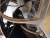
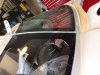
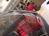
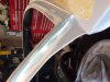
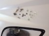
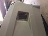
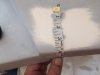
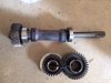
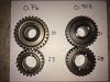
Below is a picture of the .903 gears and .767 drop gears I have (PS if anyone’s looking for .767 drop gears, I have a deal for you, PM me). Two of us custom ordered our .903 gear sets and got them within 6 weeks. I wanted to go with the .767 set, but with my GM hot cam, the low ratio would not let me stay in the RPM band I wanted for street driving, one has to keep RPMs higher with this cam. If I did not have the lumpy cam, it would have been a good choice. The .903 was a good compromise for the style driving I wanted, price,and built by Hollinger….all good. So, off to Sarasota for the install next week or so. Once installed, we will finish the tuning. I found that while dyno tune did a decent job for max HP, it really failed me on the street driving side. Once we street tuned it a bit, it stared behaving the way I want. As for the windshield to door fit, I have elected to not build up the door window to match the contour change of the front windshield. After several non-gearhead reviews, no one truly noticed the sight line change of the lower windshield corners due to the contour blending we did. Windshield fits without any body distortion.
 

Attachments

  • Gears 2.0.JPG
    Gears 2.0.JPG
    101.4 KB · Views: 470
Last edited:
Interesting - would you mind posting a few photos of what your door and windshield fit look like? I’ve been contemplating doing something similar but ask doing the door. If it can look decent without doing the doors that would be huge.
 
Here is a sequence of pics to show the buildupof the windshield A frame. In the first pic you can see how much materialwas added to the pinch weld (about 14 or so to each bottom corner, left andright). I used strips of fiberglass followed by kitty hair (fiberreinforced bondo). It was a tapered build from the top corner down andabout one third toward the front, then back to the bottom corner.
I had two choices at this point once thewindshield was flush on the pinch weld:
  • Build a ridge between the windshieldand the door to fill that space (its where I am right now). I discovered that the ridge can not be too high or it will hit the door when it opens. So, I am still playing with this some.
  • Leave it flat after the windshieldtoward the door. I’m not too crazy aboutthis as it leaves the windshield edge exposed more than I like and there is a gapthat I don’t like between the windshield and the door glass, not bad but just there. It may work out that no ridge is the bettersolution (the old material on, material off….Mr.Miyagi). I’m leaving my options open still.
With the door on and the door glass in place,it was decision time. Like thewindshield, now the door glass is off the body contour some. In my case that’s about 1/8 or less of aninch. I could leave it (looks OK actually, see picture). Or like the windshield,I could start adding glass the door pinch weld and build the door glass up tobe completely flush with the windshield. Its really not that hard, and I may still elect to do so, but its prettygood as is (IMO).


Not sure why pics went sideways, there up and down on my PC.
 

Attachments

  • IMG_2170.JPG
    IMG_2170.JPG
    98.5 KB · Views: 523
  • IMG_2184.JPG
    IMG_2184.JPG
    101.6 KB · Views: 507
  • IMG_2185.JPG
    IMG_2185.JPG
    109.6 KB · Views: 454
  • IMG_2171.JPG
    IMG_2171.JPG
    98.7 KB · Views: 477
The pics come out looking fine once you click them.

The fit looks pretty good as is but yeah, it does stand out how the door contour falls back. I suppose the door glass is flexible enough it’ll conform to the new surface without issue?

That’s a lot of work! Also a lot of skill to shape it so it’s seamless.
 
It seems like a lot of work but not really. The beauty of fiberglass is you can work it until you get exactly what you want.....wax on wax off.....had to say it. If the decision is to build up the door, The poly won’t have to bend very much at all. In fact a few small pieces of tape hold it it place. Once I get the body back in place and doors refitted, I will take a closer look at that transition. But that will be pretty simple. Based on the glass projects you have done Cam, this would BA a cake walk.
 
Last edited:
Headlight covers.....butyl them down or screw them in...that was my question. If I glue them in, I won't be able to remove and clean any dust or dirt that gets under them...so screw them. I used a progressive drill bit from Harbor Freight, #10 x 24 bolts, weld studs, and countersunk washers to get them to fit. I learned that countersink bolts actually have three possible pitches (82, 90, 100). The standard (82) proved to be too much of a head size for the washers. So I went with the 100 degree and they fit perfect. To make the holes. I taped the covers to the nose, marked the holes carefully, then drilled the holes which also marked the fiberglass. Finished the fiberglass holes with the covers off. I then put the screws in with the weld stud on the underside of the glass, and put panel bond around the bottom of the weld nut. Now I can remove the screws from the top side and never loose the nut. To add some cosmetic appeal, I built some hole covers for the rear exhaust outlets and the rear side wheel scoops. Note the outside of the wheel scoops are very unsymmetrical, but that's the pattern of the body holes. I squared up the inside of the shield and mounted screen to the back side and then took kitty hair to build a ridge around the perimeter of the fiberglass inlet to square up the lines once the shield is placed in the hole. They will be painted black eventually. Cosmetically it all looks perfect.....I really like what a little glass and kitty hair can clean up.


Off to Sarasota this week to have the drop gears installed.
 

Attachments

  • IMG_2188.JPG
    IMG_2188.JPG
    55.3 KB · Views: 457
  • IMG_2191.JPG
    IMG_2191.JPG
    139.7 KB · Views: 487

Michael Fling

Supporter
Here is a sequence of pics to show the buildupof the windshield A frame. In the first pic you can see how much materialwas added to the pinch weld (about 14 or so to each bottom corner, left andright). I used strips of fiberglass followed by kitty hair (fiberreinforced bondo). It was a tapered build from the top corner down andabout one third toward the front, then back to the bottom corner.
I had two choices at this point once thewindshield was flush on the pinch weld:
  • Build a ridge between the windshieldand the door to fill that space (its where I am right now). I discovered that the ridge can not be too high or it will hit the door when it opens. So, I am still playing with this some.
  • Leave it flat after the windshieldtoward the door. I’m not too crazy aboutthis as it leaves the windshield edge exposed more than I like and there is a gapthat I don’t like between the windshield and the door glass, not bad but just there. It may work out that no ridge is the bettersolution (the old material on, material off….Mr.Miyagi). I’m leaving my options open still.
With the door on and the door glass in place,it was decision time. Like thewindshield, now the door glass is off the body contour some. In my case that’s about 1/8 or less of aninch. I could leave it (looks OK actually, see picture). Or like the windshield,I could start adding glass the door pinch weld and build the door glass up tobe completely flush with the windshield. Its really not that hard, and I may still elect to do so, but its prettygood as is (IMO).


Not sure why pics went sideways, there up and down on my PC.

Dan,

Another option... instead of building up the door to bring the side window out to match the windscreen, consider cutting the front of the side window back about 1". Then fiberglass in front of that. Now the leading edge of the door is the window frame- not the window.
Fling SLC Build Thread
 
As I understand it, one of the drop gear installers is leaving the fold. I began a search for a shop that fully understood Graziano's, and in discussion with Hollinger Engineering (Graz gear and racing system manufacturer my post 301) they recommend Heffner Performance in Sarasota Fl (I presume its OK to mention them since they are not a sponsoring vendor). I took a trip down there to put eyes on the shop and as you can see from the picture they deal primarily with Lambo and Audi R8 mods. A drop gear replacement is kids play based on what I saw. The owner is Jason Heffner, number 941 359-0900. Give him a call if your looking for an install shop. I expect mine back next week. I believe Allan uses a gent up in the North East for his work.

In my last post I talked to the side scoops but didn't include a picture of it mounted in the hole. Here it is.

I'm working on a crude prototype of a locking system using the manual exterior and interior locking capability of the Miata door handles. I'm nearly there, but if anyone already has it solved, fess up, don't be shy.....my aging mind want to know how you did it.
 

Attachments

  • IMG_2197.JPG
    IMG_2197.JPG
    99.9 KB · Views: 469
  • IMG_2200.JPG
    IMG_2200.JPG
    66.4 KB · Views: 405
  • IMG_2204.JPG
    IMG_2204.JPG
    119.8 KB · Views: 437
Gents my apology in advance, but there is nothing sexy about this subject, a windshield washer system. I installed an ANCO 66-01 container in the nose section. It comes with its own spray nozzles, but throw them out. As you can see in my picture, I drilled all the holes you don't need too. The kit nozzles are like jet sprayers and I could not find the sweet spot. So I took a trip to my local auto parts store and discovered wide angle Dorman nozzles 47237. The wide angle covers a lot area and you can adjust the nozzle a bit up and down. As for placement I settled on a arc about 9.75" from the center of the windshield frame (see tape mark) and about 3.875 inches up from the edge. I aimed them so they crisscross a bit. Not that the car is going to see any rain deliberately, but its an OEM feature. I hooked it up to the washer sprayer on the column, and that's another story altogether.
 

Attachments

  • IMG_2216.JPG
    IMG_2216.JPG
    75.9 KB · Views: 365
  • IMG_2227.JPG
    IMG_2227.JPG
    67.6 KB · Views: 331
  • IMG_2228.JPG
    IMG_2228.JPG
    62.5 KB · Views: 418
  • IMG_2233.JPG
    IMG_2233.JPG
    120.2 KB · Views: 342
Drove to Heffner Performance to pick up the transmission with new .903 gears. While they were at it I had the AWD shaft removed and plugged. It did take some Graz case machining (~1/4 inch extension in diameter of one gear seat about two inches long). Could have been hand ground but they machined it per my request. Plug for hole came from Lambo part numbers 086311137 and 086311120 (bell housing plug and case plug about $100 each). The trick is how to install them. I had a snap ring grove cut and used O rings to seal. Installed dome light and 12V power source for cockpit.

I am using the RCR gentleman seats. Very tight fit even with the RCR door panels. Here are my covers. The upholstery shop is Shadburns auto upholstery in Macon Georgia. They should have the pattern if your interested.
 

Attachments

  • IMG_2265.JPG
    IMG_2265.JPG
    114.5 KB · Views: 486
  • IMG_2264.JPG
    IMG_2264.JPG
    107.6 KB · Views: 422
  • IMG_2263.JPG
    IMG_2263.JPG
    123.8 KB · Views: 512
  • IMG_2256.JPG
    IMG_2256.JPG
    98.2 KB · Views: 440
I was *just* looking for dome lights and haven’t been able to find one that isn’t too big. Which one did you go with?
 
Cam


May be too big for your liking, but I wanted two moveable map lights self contained at eh unit, so only needs power. Not LED.


Autotek Double 2 way 005-726-02-2
 
Thanks Dan - was thinking the 94+ mustang map lights but thought it was too big. The unit you selected is a bit big for my taste too. There’s got to be someone out there that makes a low profile LED dome light that doesn’t look like a trailer light ... I’ll just leave it on my future to-do until I can identify something that fits the bill.

How are you making out on the door locks? I spent a good amount of yesterday working on doors and settled on manually locking/unlocking via key from outside. I had wanted to implement door lock actuators too but not happy with implementation/risk of accidental locking till I can find enough time to do it right.

Did you re-key your lock cylinders?
 
Gave up on integrating inside with outside locks. Going have individual systems with hidden unlock Incase inside would lock itself even though it should never happen.
 
Gents

I am transitioning to a mechanical signal to the VSS in the ECU (vice Dakota Digital). I/we have three choices for reluctor rings that I'm aware of, 1. press fit on the hub 2. Factory Five style ring 3. Porsche ring. After some deliberation, I went Porsche style. It has the fewest teeth but was easiest to cut in two and mount with the CV heat shield I also installed. Since the ECU can be programmed to PPM, I will do so via a tuner. I had the mount machined and will add a heat shield to protect the sensor. Its plastic vice aluminum (bad choice maybe), but I will see how it works soon enough.
 

Attachments

  • IMG_2271.JPG
    IMG_2271.JPG
    112.4 KB · Views: 412
  • IMG_2273.JPG
    IMG_2273.JPG
    114.8 KB · Views: 464
I'm in the final stages of the final assembly catching the little things that haunt you. After installing the tail for the hundredth time, I noticed some stress cracking in the glass near the hinge mounts. Perhaps you noticed it before I did, but from the bar mount up the tail, there isn't any real support to carry the weight. I explored two options, both viable . Use fiber glassed structural supports in strategic locations to stiffen the very bottom of the tail up the backside to distribute the tails weight over a larger area, or build a metal frame to carry the weight to the frame via the "J" hinge. I went with metal as seen in the picture. Once installed, I put my full weight on the tail and it didn't budge. There is a convenient shelf under the license plate that I used to set my crossbar under to catch the weight. The ends of that bar are screwed into a plate that is bonded and glassed into the body. The second minor issue was to make a switch I could reach the battery cutoff from inside the cockpit. I had originally thought having it under the bonnet would be OK, however I began to realize that every time I wanted to cut power, I had to raise the bonnet. So I connected a rod as shown in the pictures and routed it behind the passenger seat. Simple I out operation. Acts as a bit of a theft deterrent if you don't know its there (but I guess everyone knows now). So I'm getting her ready for state inspection.
IMG_2309.JPG
IMG_2313.JPG
IMG_2312.JPG
IMG_2307.JPG
 
Here is a mod that may be of interest to you:

The situation for me was the Olds steering column would not pull further away from the instrument panel to engage the bright lights. When the light stick/rod was pushed forward, it hit the IP. There is a slotted hole on the Olds column but not on the aft bracket, so I opened the slot on the back bracket. The real issue surfaced with the double D shaft attached to the universal joints at the end of the steering shaft. Its a solid rod with "keyed" slots for the universal bolts. Hence impossible to adjust. In the picture you will see I took the double D shaft and cut it in half. I then took a 4 inch piece of double D female tubing and welded it to one half of the rod. The other end inserts and now can slide without any interference in moving the steering shaft. I lubed it to prevent it locking up, but its really tight and creates a vacuum so there is no play. Problem solved. If anyone else has this problem, this worked very well.

IMG_2331.JPG
IMG_2332.JPG
IMG_2333.JPG
 
Its nearing the 3-year mark. Car passed state inspection. Now to dismantle for paint.
I blogged about several issues that I have resolved and here is what I discovered, which may help those still in build:
  1. This was a self-inflicted wound. I originally had Wilwood master cylinders, that no matter what I did they would leak. I had driven the go-cart with Wilwood installed. Changed them out for Tilton and maintained the same diameters. Once installed with engine running, I could not get the car in gear. I adjusted the shaft length to increase the throw hence push more fluid. Apparently, there was just enough size difference that the ¾ inch Tilton would not disengage the clutch. Solution, bought larger diameter Tilton clutch master (7/8) and all is well.
  2. Fine tuning the doors has been the most time-consuming adjustment on this entire project. I used painters sticks in strategic locations to maintain the spacing. When you look very closely at the movement of the J hinge on the door, you will notice that the best adjustment for the heim joint is SHORTER not longer. I made it as short as possible to avoid hitting the nose section at the 90-degree corners. I need to state the obvious, but when you adjust the front spoiler elevation, ensure its high enough to force the nose to sit flat on the most aft pin on the nose to main body. You need all the space available to get the door over that section of the nose. There is some shaving required in the door section to avoid the impact. Adjust the doors with the tail section on as well. Don’t adjust the tail too far forward as you will hit the door. Pushing the door too far aft will cause the bear claw to impact the body, so use the claw as an adjustment point as well. Setting the striker pin is another critical challenge. With the bear claw closed, I drilled a small hole in the center of the closed claw so I could shove a stiff wire/probe thru that hole to hit the striker area of the body and leave a mark. I used clay to leave imprints of the probe mark and to see the path the claw was taking on its way to the closed position. It’s a very, very small margin for error. Once adjusted, I drilled a ¼ hole thru both the compression plates on the door and locked them into place. Now the door will not move and become misaligned. Highly recommend you spend some time to add reinforcement glass along the interior edges of the door where the hinge compression plates sandwich the door. It’s a very week area.
  3. I am using the RCR gentleman seats, and had custom covers made. The passenger side cockpit space is about two inches narrower than the driver side; hence the passenger sits closer to the door. With the RCR provided interior door panels, its very close to hitting the seat. Instead of cutting the seat, I cut a pocket into the door panel to allow more room for the passenger seat.
  4. I gave serious consideration to the quick latch lock down in lieu of the aero latch. In fitting the body, I noted that the aero latch gave me more positive holding force to help hold the nose and rear hatch down on the pins nearest the doors. This was beneficial in adjusting the doors. The quick latch may have worked just fine, but I never got that far.
  5. Drove the car with the new .903 drop gear. Pleased with the drivability. If I had to do it over, I would pay more attention to the engine cam. I want good street manners and I do not like the behavior of the GM LS3/480 package. I would have enjoyed the basic 430 HP cam more. It may get changed out one day, but not today. Tuner says we have more work to do and he can settle it more.IMG_2439.JPGIMG_2429.JPGIMG_2256.JPG
 
Back
Top