Economical 2 stage EFI fuel system for the DIY Guy

Lynn Larsen

Lynn Larsen
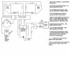
For those who don't race their GT40s and don't mind saving a buck or two, I thought I would share an economical system I have put together. The issue I was trying to deal with was my high pressure EFI fuel pump sucking air under heavy braking or sustained down hill stretches when the fuel tank being used got under ½ tank. EFI rated fuel pumps DO NOT like to pump air and it doesn't take long before doing so can destroy one of these not inexpensive units. The solution that best follows the KISS principal (and has been discussed here before) is to create a 2 stage fuel system where the first, "low pressure" stage pumps fuel from the GT40's long, skinny tanks into a smaller swirl pot or header tank from which the second, "high pressure" stage pumps fuel to the fuel rails feeding the fuel injectors. The pressure in the second stage is controlled by a bypass type fuel pressure regulator as is common with virtually all modern EFI engines.

A word about the term "high pressure" with respect to EFI fuel systems: of course, "high pressure" is a relative term. And, when compared to the ≈7 psi that carb systems run at, the ≈36 psi that EFI systems run at is relatively high. But, this is not something that should scare anyone away from working on their fuel system. After all, these pressures are those commonly found in your household, potable water system; and, most of us wouldn't consider our faucets as working under "high pressure." The mystic of the "high pressure" EFI fuel system has been perpetuated, IMHO, by the industry as more than one company has made huge amounts of money selling their "exotic" systems (he says with tongue firmly planted in cheek) for wildly inflated prices.

The trickiest part of putting this system together was, believe it or not, in picking the fuel filter to use in front of the low pressure pump. The first stage of the fuel system MUST be able to keep up with second stage to assure that the swirl pot/header tank always has enough fuel in it prevent the "high pressure" pump from sucking air: the whole reason for this exercise. The "tricky" part of this is that virtually none of the economical fuel filters that are suitable for the first stage of the system have available flow data. I called several of the companies who actually make the filters and most simply stated that they didn't have that information. For the few who gave me a number, I'd bet dollars to donuts, that it was a help desk guy taking a SWAG at the value. According to Aeromotive's FAQ, the most common error in setting up fuel systems in general is using a pre pump filter that is too fine and/or with too little surface area: they recommend 100 microns with 6 square inches for their EFI pumps. If you do a little research, you will quickly see that the value point for fuel filters is quite important because one can easily spend as much on a fuel filter as one would on a reasonably price fuel pump; there just seems to be something inherently wrong with that fact.

Heat saturation of the fuel is another issue that plays into the design of a system; but, since we are designing for a street car and not a race car, this gives a little more latitude. The second stage fuel filters sourced from Mr. Gasket* are billet aluminum units that are finned. If these are placed in or near a outside air stream (like near one of the two big rear clip scoops) this will help dissipate heat from the fuel on its way to the fuel rail. The other question raised by heat concerns is whether to route the return lines to the swirl pot/header tank or to the main tanks. Again, since we are designing for a street car and quality of the fuel for the EFI system is the major concern, it was decided to take advantage of the anti-aeration return port on the RCI 1 gallon aluminum tank being used as the header tank.

*As an aside on these second stage fuel filters: I used these on my initial, single stage EFI fuel system. However, when I bought them, they were being sold by K&N. I called K&N since I could no longer find them in catalogs or on the K&N website and I couldn't remember what the micron rating was for the pleated, stainless steel filter discs that they use. The lady at the help desk said that she no longer had data for the filters, so I asked her for the name of the supplier who K&N obviously OEMed them from. She dutifully took my name and number, saying that she would have to get back with me on that. Meanwhile, I am thinking, "yeah, right! This is the last time I'll be talking to anyone from K&N." Amazingly, about 45 minutes later, she calls back and tells me that the filters are made by Goran Products in California, Golan Products - Award winning high performance products for your racing machine, who can be reached at 310-630-5858. This would turn out to be fortuitous since Mr. Gasket, who now retails these nice looking parts, only supplies them with 10 micron filter elements. Goran can provide a 60 micron element, so I ordered two for use in the pre pump filter recalling what I had read on the Aeromotive website. (Bye the way, these filters can be assembled so that the fuel must pass through the filter or they may also be assembled so that, if the filter should become full, the fuel can bypass the filter. For a racer, this could mean the difference in finishing the race or having the engine starve for fuel and quit with the checkered flag within sight!)

Some may question the choice of the MSD EFI fuel pump and I must admit that it was probably the most edgy decision made in putting the system together. But in looking at the choices without the use of rose colored, mystical glasses and with the fact that MSD does have reputation to protect, the $95 price tag just couldn't be ignored when pumps of similar flow and pressure ratings can easily sell for 300% of this price, and some go for as high as the $800 dollar range. The biggest draw back for me was the fact that the pump employs hose barb fittings rather than the -8AN fittings I would have preferred. I did email MSD technical support to see if the fittings were replaceable, but I have not heard back from them as yet. I suppose I will have to give them a call as I have found that, in general, email tech support is a dicey proposition.

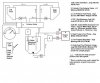
Hopefully, you will find the following diagram fairly self-explanatory. There are surely hundreds, if not thousands, of possible combinations and permutations of components that could be assembled to produce a fuel system similar to this one. So, keep in mind that this is just one of the possible ways to do it and it may not contain the trade-offs of brands, pricing and real/perceived quality that you would have made.

Regards,
Lynn
 

Attachments

  • 2stagefuelsystem.jpg
    2stagefuelsystem.jpg
    43.8 KB · Views: 1,064

Ian Anderson

Lifetime Supporter
Well said Lynn!

I have a similar system on the DAX
But I run a single LP filter after the Pollack valve / selector and a lot smaller swirl pot (about1.5litres)

Heat build up is a bit of a problem and U have heard from another forum that the small UK style delivery vans (Diesel) use a small radiotor in their return from fuel rail to assist with the cooling

I will see what I can find next time at the breakrs befre buying a new unit for the car

OK I am running a 3.9 Range Rover engine and run a Facit Red top on the Low pressure and a Bosch HP pump for the EFi (Said to be good to fuel for 350 hp) Yes at times the Facit pump hammers on air whenyou brake on a 1/2 tank of fuel but the engine is always fed. The Swirl pot would run the engine for about 3 minutes at idle (We did it in error as I filled one tank with fuel and was drawing from the other (empty one))

Cheers
Ian
 
I helped a friend setup this type of system in his Cobra. He's running a 514 CI engine with the TWM injection at almost 800HP. We added a one gallon swirlpot and plumbed -6AN from the main tank through a pre-filter and low pressure pump to the swirl pot. From the pot we added the -10AN line to the high pressure pump then post filter. (both were Aeromotive). We plumbed the -8AN return line to the swirl pot and added a -6AN overflow from the pot to the main tank return line fitting. This way the low pressure pump only needs to keep up with fuel actually being used as the return line helps keep the pot full and the high pressure pump airless.
It has worked out fabulously with no starvation problems.
A side benefit was it increased his fuel capacity as the original SPF tank only held about 16 gallons.
 
Some of the high pressure pumps require a small amount of pressure on the input side. This would require either a pump between the swirl pot and the HP pump or mounting the HP pump below the pot to let gravity provide the pressure. Has anyone had any issues with this?
 

Randy V

Moderator-Admin
Staff member
Admin
Lifetime Supporter
Nice drawing Lynn - I think I'd run the return line from the pressure regulator back to the selector valve which would then re-direct the returning fuel to the tank that is currently feeding the system. Otherwise your surge tank will fill up while the car is idling and there will be no place for the un-spent (returning) fuel to flow..
 

Lynn Larsen

Lynn Larsen
Randy,

The fitting that is ordinarily used as a vent on the fuel cell is plumbed back to the selector valve for return to the proper tank. So as the swirl pot fills, it spills back to the main tank. (I had thought about color coding the lines in the drawing because of possible confusion that this section of the diagram might cause with the way the lines cross.)

The return from the FPR is sent back into the swirl pot via the anti-aeration port which extends down into the bottom of the tank so the return exits under the surface of the fuel.

Eric I have read a warning on some HP pumps that they will NOT lift fuel. So, you can't use a sump tube that enters via the top of the tank with them. Some simply state that they are not self priming which implies the same thing. These should be mounted in such a way that gravity keeps the pump primed.

Regards,
Lynn
 
Last edited:

Ian Anderson

Lifetime Supporter
Randy

As stated above I used a small swirl pot (1.5 litres compared to Lynns 1 gallon monster)

I looked at doing a T out the top of the swirl pot (So the air bleed on the low pressure side) can also return via the pollack valve to the corrct tank along with the returned fuel from the fuel rail.

But I was unsure how often the low pressure unit would be pumping air and hence the HP pump would be emptying the swirl (direct to main tank and not to swirl). Possibly under hard power on cornering with low tank fuel level???? So I decided the safest option was to return the fuel rail to the swirl.

It is definately worth finding out the flow rates of the pump you will use and find out how quickly it can empty the swirl withot the swirl being refilled..

I also ran a 6mm pipe as a return to the pollack valve (8mm pipe from the tanks so the reduced tube results in a small presurisation of the swirl and hence positive feed to the HP pump.

This in turn raised a question in my mind - if the swirl is at say +3psi pressure and the retun from the rail to swirl is full, will that mean that the preset pressure regulator will be runnig at 3psi higher than it was set for? Professionals on the engine I am using said not and I accepted it. (Still could not figure out why not) - It does not appear to have any adverse effect.

All the fuel plumbing is mounted onthe lower space frame chassis (Low pressure pump, pollack, swirl and HP pump) so the pumps should be below fuel level except on the lowest of tank levels.

Ian
 
This in turn raised a question in my mind - if the swirl is at say +3psi pressure and the retun from the rail to swirl is full, will that mean that the preset pressure regulator will be runnig at 3psi higher than it was set for? Professionals on the engine I am using said not and I accepted it. (Still could not figure out why not) - It does not appear to have any adverse effect.

Ian,

The fuel pressure regulator will reference directly to atmostphere, not to the return pipe. Thus if set for x psi pressure, it will allow sufficient (within design limitations) fuel to bleed into the return line to drop the injector feed pressure to x psi above atmospheric pressure.

Provided that the return line can physically carry that volume without developing undue backpressure, the regulator system will function correctly.

In order to assure this, the return line should be as short as practical, and appropriately sized.
 

Lynn Larsen

Lynn Larsen
As I speculated, MSD did not respond to my email, so I called them. It turns out that the inlet port for the MSD high pressure pump can be replaced with an AN fitting. The outlet hose barb is built into the pump and cannot be replaced.

The idea of the Carter low pressure pump costing more than the high pressure pump has been gnawing on my skin flint nature. Does anyone have a recommendation for a low pressure pump that is: reasonably priced, quiet, reliable, relatively small, and has a modest current draw?

Dave Wharran used a Walbro pump that appeared to fit the bill but appears to be out of production.

Regards,
Lynn
 
Lynn,
Haven't looked too closely at them, but I did run across a web page that lists the Walbro replacements for the discontinued 6000 series. They "Can be run dry for up to 4 hours, self priming up to 48 inches, < 2 amp current draw".
Prices listed look reasonable.

Walbro Reciprocating Fuel Pumps

Dave
 

Lynn Larsen

Lynn Larsen
The new Walbro FRx fuel pumps come in two flavors: in one, the fuel flows at all times that power is supplied to the pump. In the other type, the pump turns on when fuel is needed (back pressure falls below a preset.) This is also the behavior of the Carter rotary vane universal type fuel pumps.

This "on demand" behavior begs the question, "should some sort of flow control be incorporated into the swirl pot or should the pump be allowed to supply fuel continuously and the excess returned to the main tank in use?" (The return line is a given, so that aspect is not in question.) The advantages of the continuously running setup include simplicity and a dilution of the heat in fuel in main tanks. The disadvantage is that the pump runs continuously - making noise, using power and adding some finite amount of heat itself.

If one were going to have flow control, the question then becomes how to achieve it. One could use a pressure regulating valve on the return line, but I'd really rather not pressurize the whole system to control the fuel pump. So, a float valve of some sort seems to be the obvious solution. The $64K question is where does one find a suitable valve (or assembly) that lends itself to installation in a header tank? I have found some brass bodied float valves in the 3/8" size range, but these, as most I have found, are designed for flow control of water. The float material is the biggest potential problem with these (float arm length could also be a problem, but should be fairly easy to deal with.) retrofitting some tanks may also be an issue, but for the fuel cells with round, aviation style caps, it should not be an issue.

Thoughts and/or suggestions anyone?

Thanks,
Lynn
 

Ian Anderson

Lifetime Supporter
Lynn

I think you may be barking up the wrong tree.

My ECU Range Rover unit from 1990 has a few relays connected
1)Turn on ignition and the pump circuit is activated for about 3 seconds to prime the system.
2)Until the engine is cranked the pump will not run again
3)Crank and the engine fires up
4)It is then using fuel so the low pressure pump will always be running.

Stall the car and the pump runs for 3 secs and stops

So this is the same as a carb fed car - turn on the ignition and the pump will run and fill the carb, (same as 1) above)Do not crank the car and except for evaporation the pump will no longer run, (Same as 2) start the engine and the pump continuously refills the carb (Same as 4) above)


Surely any ECU uses this type of circuitry to stop a HP and high volume pump from creating a fire hazard by pumping fuel when the engine has stopped due to a leak in the Hp side causing he pressure to not fuel the engine.

Also now in real life on a 1/3 tank brake and the ;ow pressure pump will pump air With yourpressurised sysem there is nowhere for the air to go - and the float level thing would mean havng something venting to air to let such air escape - a gallon pot in your case with an open vent in a roll over - sorry not my idea of fun! (Carb floats have a lot smaller volume on the bowl)

Cheers
Ian
 

Lynn Larsen

Lynn Larsen
Ian,

To clear something up that my writing style evidently caused: I was not proposing the use of a pressure relief valve and float valve together. What I was trying to say was that one OR the other could cause an on demand fuel pump to cycle on and off.

You are spot on with the issue of venting that a pressure regulating valve would raise. Not only is this true on the positive pressure side of the equation, which you described, but it would also be true from a negative pressure point of view. If the HP pump was a positive displacement pump (which would make it self priming as well) and you ever got down to using that last gallon of gas in the pot, the tank would be in real danger of being sucked down to ball of cumpled aluminum because of a lack of venting. With most real world HP pumps for EFI, they would simply stop pumping in relatively short order.

In the closed header tank system in the drawing, the return line, via the main tank vents, is effectively the vent. Through the use of a float valve ONLY, this would continue to be true.

As to wiring the low pressure pump, your scenarios assume that the same power (ECU controlled) is used for both the HP and the LP pumps. While the same signal could be used to engergize two separate relays for each pump, I don't think it would be a good idea to run both through a single relay. Indeed, I plan to use a separate switch to control the LP pump relay so that I can prefill the pot prior to starting the engine. This could be done procedurally if the LP pump activation is energized with the ignition switch; but, I have seriously considered mounting the LP pump switch in a hidden location for anti-theft reasons. (Any would be thief would only get as far as the existing fuel in the header would take him.) For safety reasons, the diode protected grounds for the relay activation circuits will both pass through the inertia switch that is already in use. (The '93 Ford EEC-IV ECU does not have an oil pressure cutout for the fuel pump relay control; but, I may add this to the inertia cut out switch for added protection.) I will very likely also mount an indicator light near the fuel pressure gauge (HP) which will show when the LP pump is activated, especially if I put float valve conrol on its output.

So having an intermittent low pressure pump is technically feasible and I am sure there are going to be plenty of times when the LP pump can stay way ahead of the HP pump. But, just because it can be done, I am still not sure if it should be done. First and foremost, it violates the KISS principle! And, I am not convinced that the heat dilution gained from constantly returning the overflow to the main tanks is overshadowed by less noise, less heat generation and less power consumption of non full-time operation.

Lynn
 

Sandy

Gulf GT40
Lifetime Supporter
Lynn -

I just caught this thread, and you have (with the bleed back) pretty much what I was going to run for the surge tank. I have one of the Mechanical 4 port valves but other then that looks like what I was thinking. The one thing that I was working on and haven't had a chance to finish was the variable speed pump controller (PWM). They have a couple of commercial ones but they are somewhat expensive (Aeromotive). They key of off RPM and bring the excess fuel circulating a bit more under control by reducing fuel rate at lower RPM. I'm Running a carb now so not much more to do but will eventually get the EFI going on the car. One thing to watch out also is flow in the return lines. If you do have a crazy big efi pump you may still not be able to bypass enough fuel with some of the electric valve so I'm told. For me the PWM controller solves that as well as needless churning of the fuel. I'm also going to try to use the low pressure pump (regular carb pump) to suck through the tank selector valve (-8's) and see if it works so only one of the low side pumps is needed. Not sure how it will work, but will give it a try. Some of this was in an old thread too, and one of the members has a part that is suppose to make this all unnecessary except that it can't work in a GT40 with the way the tanks are. In the 40's I'm pretty sure you will need a surge tank (swirl pot) internal or external for EFI if you want it to work well.

Sandy
 

Ian Anderson

Lifetime Supporter
Lynn

Apologies if my writing raised an eyebrow - it was certainly not meant in that manner.

I am running both pumps od a single relay so your comment is worrying but it works so I;ll stick to if it ain;t broke don;t fix it but would appreciate your comments as to why 2 feeds / relays would be better

The pumps circuit on the Ecu picks up a trigger in the distributor and so long as the engine turns it keeps power to the pump - engine stops no distributor signal and 3 secondslater pumps turn off (Lucas 14CUX Ecu)

I must say I had not thought about the negative crush on a swirl but it could happen

I like te idea of Sandy's speed control fuel pump but again think a bit overkill - it is when you are at idle that the most fuel returns to the swirl and thus will heat the fuel the most - it is then at this time that you need
max LP fuel flow to take the "warm" fuel back to the heat sink / tank

Sandy I run 2 pumps only the LP "Sucks" from the tank through the Pollack and then feeds the Swirl and the HP then feeds the fuel rail.

I also cannot see how a Mega EFi pump will cause a flow back problem to the tank - the Efi pump should return to the swirl. This in effect makes 2 fuel circuits Ine LP Tank LP pump tank (via the Pollack valve - and max return is the flow of this pump, the second circuit is Swirl to fuel rail and back to swirl If however you chose not to return the fuel rail to the swirl a mega EFi pump could empty the swirl while the LP is sucking air. - This in turn could ;ead to a return to tanl problem.

I'll also like the KISS scenario - and would be on cards if the part built car did not already ave EFi

Ian
 

Sandy

Gulf GT40
Lifetime Supporter
Ian -

Sounds like your are doing the LP pump and letting the Pollack valve do the switching, I like that and anything to get rid of an extra pump is good.

No sure if this is what you were saying, but after talking a bit with one of the pump manufactures about the pumps I have (SX Perf inlines), they commented that the return line should be -6 minimum and not restricted since the pump has a lot of volume and pressure. It would not really matter if the swirl pot was in the equation or not, ultimately the return will have to carrier the normal High pressure return. Another interesting idea was to pressurize the swirl pot, but came up with the same conclusion that it would just collect air and not work. The SX Performance pumps and other can be fed with a low pressure pump as the tech told me. Another issue that I thought might be a problem is if the HP pump is pushing back a lot of fuel into the pot, and the returns have restrictions it may have to have a check valve on output of the LP pump, might be over thinking, but that is a known problem I have :)

One question I never really thought about was what was the acceptable minimum size of tank that could be used. A gallon seems large, but don't really have a feel for what it might need.

The crash worthiness was also a concern and I'll likely make something out of rectangular or round heavy wall aluminum pipe vs. Sheet metal like ATL's and others (It's also easier to weld then the thin tanks).

The KISS principal would be to use just one tank and it would clean up lots of stuff, but as you know we have to add something to do and making it too easy would not be in the spirit of things :D

Sandy
 

Ian Anderson

Lifetime Supporter
Sandy
Yes that is correct

I have the set up
Tank - pollack - Facit Red - filter - swirl - tank
Swirl - Bosch HP - Fuel Rail - swirl

At no stage does the high volume high pressure hit the pollack - it only sees the low pressure side of the system.

When the engine is turning both pumps are pumping - hit the cross over switch and only the pollack moves (Along with picking up the fuel level float level from the other tank to a single fuel gauge)

My Swirl pot is about 1.5 litres

I'll see if I can get some decent pictures of it this weekend

I also thaught long and hard about volume of swirl and decided small was OK as it would be coninually circulated to the swrk and the LP would pump air on braking - generally when the engine is on overrun and not using a lot of fuel.At Idle it will last a good few minutes on the 1.5 litres. By then I should be off the brakes! Long downhill - well I've never encountered it yet!

Ian
 

Lynn Larsen

Lynn Larsen
BTW,

I redid the drawing to make the return circuits a bit less confusing than the original.

Sandy, I never really considered the possibility of the HP return overpowering the LP supply, but if your EFI pump has that much output (both flow & pressure), I suppose it is a possibility. If that is indeed the case and in order to remain in keeping with KISS, you may have to return the HP side directly to the main tank via it own lines and would certainly preclude the use of Pollack valve. Determining that the LP side can keep up with that will also become very critical since it would seem quite plausible that just any old low pressure pump might not be able to. The Carter 100 gal/hr pump shown in the drawing is at the high end of range of typical carb type pumps of modest cost.

All of that said, I can certainly see why you are looking at a pump controller. MSD also has these for sale at prices on par with what you mentioned. For a drag racing engine that must be able to idle at one moment and then output HUGE horsepower the next, I can see why a pump with enough capacity for the high end with a controller to throttle it back for more mundane operation is needed. But, for a road race engine that operates in a narrower band of power output, wouldn't it make more sense to use a pump whose output more closely matched the requirements? Do you really need that extra capacity or does it come along with other qualities that this pump posses that others might not?

Regards,
Lynn
 

Attachments

  • 2stagefuelsystem.jpg
    2stagefuelsystem.jpg
    43.7 KB · Views: 501
Back
Top