Electronic turn signals

Neil

Supporter
Some time ago I was wiring a car and I wondered why I did not find an electronic solution to turn signals and flashers. Some digital logic, an astable timer, two relays, and a handful of small components can do the job. Any good technician can lay out this circuit on a small printed circuit board. It can vary the flasher frequency by changing the value of one capacitor and the turn signal indicators can be incandescent lamps or LEDs. If the P-channel MOSFET is sized appropriately, it can drive even heavy loads if necessary. I've attached two PDF files to show the circuit and how it works.

"Turn Signals Diagram" is the overall circuit. "Turn Signals 2" is a modification that allows the circuit to be simulated on a computer. The resulting waveforms are shown on the second page.

I could add an "Emergency Mode" flasher if anyone is interested.

If anyone has questions, let me know. Feel free to copy & build it as you wish.
 

Attachments

  • Turn Signals 2.TSC - TINA.pdf
    68.3 KB · Views: 319
  • Turn Signals Diagram.TSC - TINA.pdf
    44.6 KB · Views: 210

Steven Lobel

Supporter
Looks really cool. Would love to see Hazards in there and then a You-tube video and parts list with lots of pics for those of us who are not electronically inclined.
 

Davidmgbv8

Supporter

I have used this and it works great!
 

Neil

Supporter
Actually, adding a "Hazard Mode" was easy- just use a DPST switch to short each of the momentary pushbuttons for Right and Left turn signals. The lamps will all flash until the switch is turned off.
 
Some time ago I was wiring a car and I wondered why I did not find an electronic solution to turn signals and flashers. Some digital logic, an astable timer, two relays, and a handful of small components can do the job. Any good technician can lay out this circuit on a small printed circuit board. It can vary the flasher frequency by changing the value of one capacitor and the turn signal indicators can be incandescent lamps or LEDs. If the P-channel MOSFET is sized appropriately, it can drive even heavy loads if necessary. I've attached two PDF files to show the circuit and how it works.

"Turn Signals Diagram" is the overall circuit. "Turn Signals 2" is a modification that allows the circuit to be simulated on a computer. The resulting waveforms are shown on the second page.

I could add an "Emergency Mode" flasher if anyone is interested.

If anyone has questions, let me know. Feel free to copy & build it as you wish.
I would love to trigger my turn signals by just bumping the switch and have it flash 4 times then self cancel. My van does three flashes but I want one more flash. Anyone know how to do that?
 
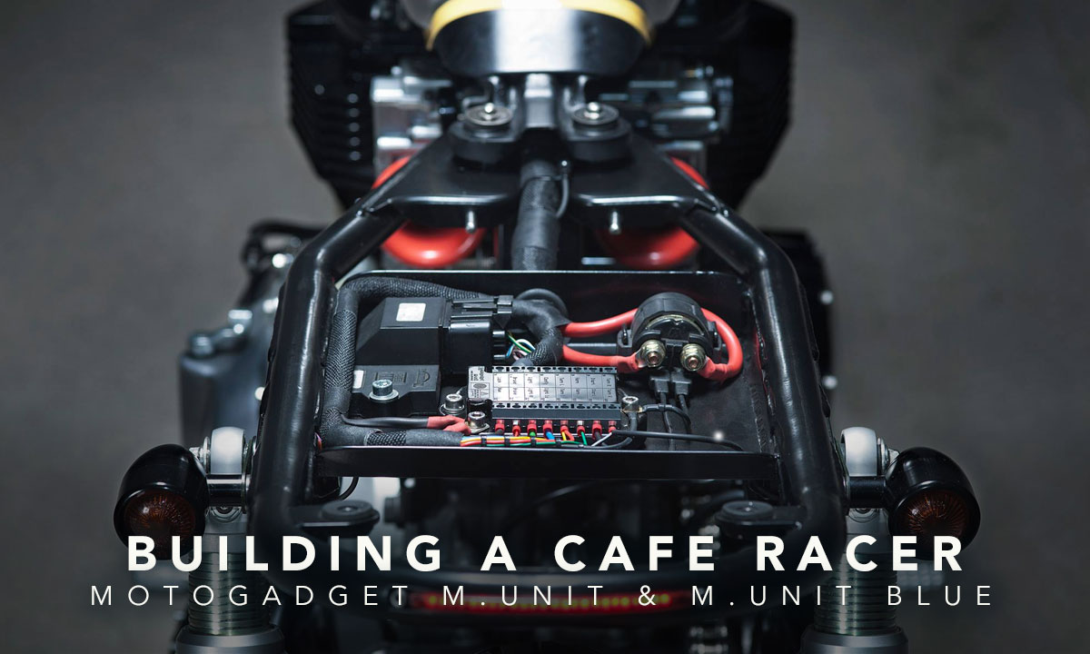
I'm planning on trying out the Motogadget Power distribution module. A programmable logic board, with software interface. Also houses built in fuses, relays etc. Very small and useful for a dasboard module, simplifies wiring greatly.

 
Back
Top