FEA Goes Mainstream

Chris Duncan

Supporter
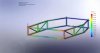
Solidworks FEA, comes with the basic package. Finite Element Analysis, or load testing finally available to the general public.

tubing is ALL .083" wall 1.5" sq. 1021 steel, the pan is .025" of the same steel.

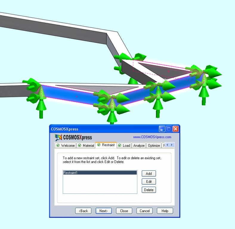
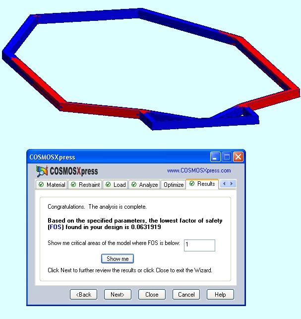
The first test is on the bottom section of a typical GT40 Chassis, a little less than the amount of material you would find in a ladder frame Cobra. These are the anchor areas. Like if you're doing a torsion test.
1_01-ANCHOR.JPG


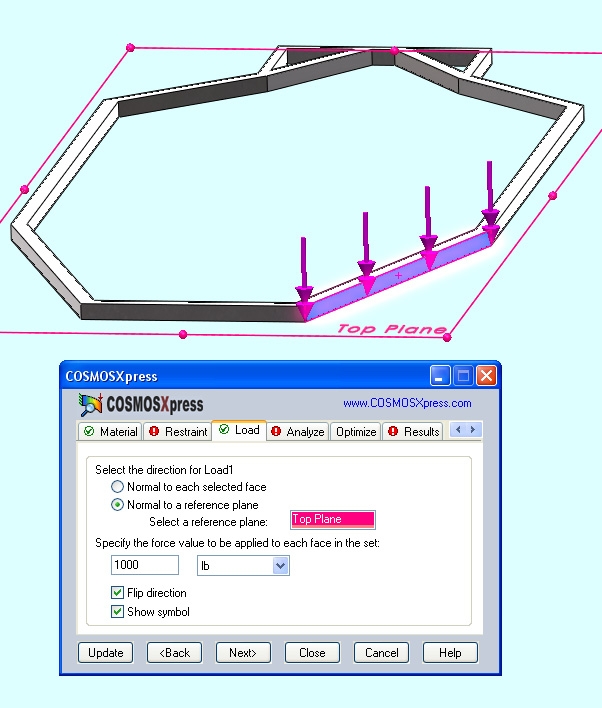
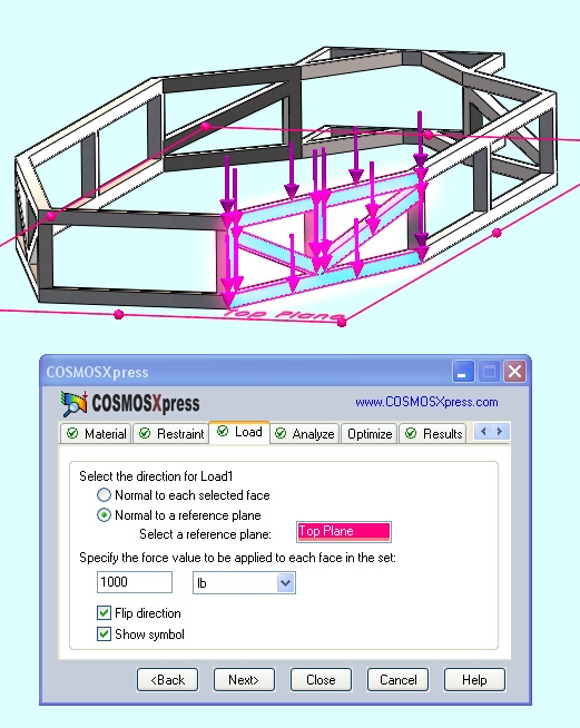
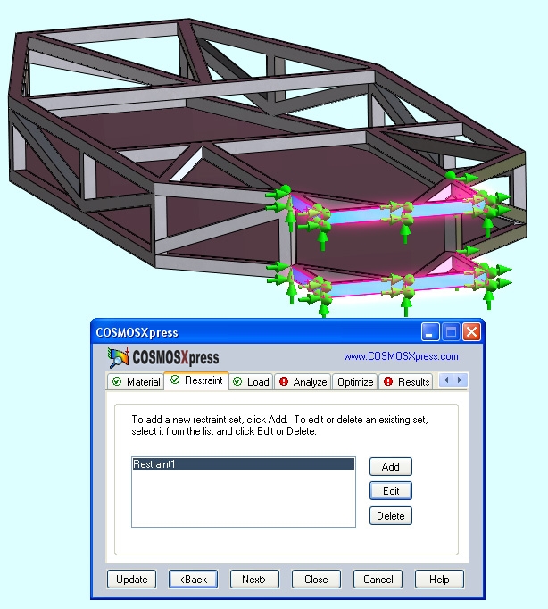
Here's the load area. 1,000 lbs is the amount of load we'll be testing with.
1_02-LOAD.JPG


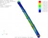
Here's where the failure is located and the percentage of load that it started to fail, about 6%, or 60 lbs. pretty low.,
1_03-FAILURE.JPG


Add the top rail and part of the diagonals on the side
1_04-LOAD-2.JPG


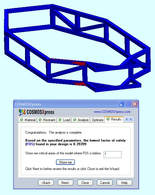
This gets us up to about 40% of the load or 400 lbs. The FOS (factor of safety) should be about 1.5. In other words 1.5 times the load or 1500 lbs. This gives you a margin.
1_05-FAILURE-2.JPG


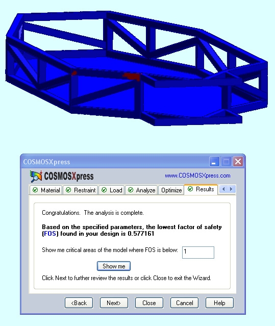
Add a floor pan and full diagonals on the sides. The fail point is getting really localized and the pan takes care of the bottom failure area. Up to 57% of the load or 570 lbs.
1_08-FAILURE-4.JPG


Add some top tubes with diagonals
1_10-ANCHOR-5.JPG


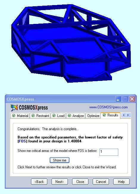
success, holding 1.4 FOS, or 140% of the load before failure. 1400 lbs. The model at this point weighs 175 lbs.
1_11-SUCCESS-5.JPG


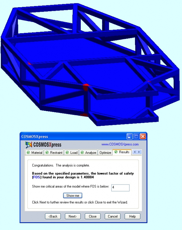
Add more weight to see where it fails. Here's 4 times the load or 4,000 lbs. The failure is very localized and you can see what a weak point really looks like. The larger one is a section change where the width of the chasssis abruptly changes from narrow to going wider. The other fail point is where a cross member comes in at the middle of the side tube instead of at a junction point.
1_12-FOUR_TIMES.JPG
 
Last edited by a moderator:
Hi Kalun,
I am currently doing the same thing, however have not got as far as this!
Have you drawn your chassis using weldments? This tool makes life a hell of alot easier when drawing up structural frames, however you have to initially draw your chassis using single lines located in the centre of the tube you are drawing (however this tool wont work with poly lines as of solidworks 2008)

You initially construct a cross sectional drawing of your tube with radius's and thickness and it essentially extrudes it along all the lines you selected. This also allows you to easily alter the whole chassis's tube thickness to find the optimum weight/strength ratio.

The other benefit is that FEA calculates the loadings on the chassis and takes the welds into consideration. However when selecting structural FEA analysis for use with weldments i couldnt get it to analyse my drawing with gussets :(

A great time saving feature of weldments is it automatically creates a cutting list, saving huge amounts of time!

Here is a picture of my chassis under structural analysis in FEA using weldments.
 

Attachments

  • new chassis1-study 1-displacement-displacement1.jpg
    new chassis1-study 1-displacement-displacement1.jpg
    18.9 KB · Views: 271
Yes Kalun D FEA in Solidworks is pretty cool. As a mechanical engineer I can say that these tools are fun but can lead to misleading results if not used correctly. In Australia the requirements for certification are very strict and if the torsion and bending reports etc. for my RCR are not forthcoming (reminds me to follow up RCR again for some reports) I will need to do such investigations and commission physical testing to satisfy the engineer approving my vehicle.

suspension-practice-cosmosxpressstudy-displacement-plot2.jpg


A practice analysis like above (RCR front upper arm CAD model that I created from measuring a part) is fairly quick but determining the forces that should be applied and boundary conditions can be tricky to set properly. Getting my engineer to accept such things will take some work that I hope to not have to do!

Have fun though, they are great tools.
 
Last edited:

Chris Duncan

Supporter
I am currently doing the same thing, however have not got as far as this!
"Have you drawn your chassis using weldments? "

No, just a profile from the side, then a 1.5" extrude then shell. I'll have to look at weldments.

" couldnt get it to analyse my drawing with gussets "

Yeah, I've noted some limitations, like no multiple load points.

"Here is a picture of my chassis under structural analysis in FEA using weldments."

How did you get the load in 2 different directions? What are your tube sizes and amount of load?
 

Chris Duncan

Supporter
"As a mechanical engineer I can say that these tools are fun but can lead to misleading results if not used correctly."

Firmly agree. Virtual testing gets you in the ballpark, then confirm with physical testing.

"In Australia the requirements for certification are very strict"

Some of the states have inspections but there's absolutely nothing in Washington state. Travel the roads here at your peril.

"A practice analysis like above (RCR front upper arm CAD model that I created from measuring a part) is fairly quick but determining the forces that should be applied and boundary conditions can be tricky to set properly."

Agree again, the tool is only as good as the person using it.
 

Trevor Booth

Lifetime Supporter
Supporter
Be very careful using FEA as the basis for design unless you understand it 1000%

A motor vehicle is a dynamic structure and should be designed on fatigue
Factor of safety is NOT the way to go. You need to extablish a design life expectancy and hence the number of fatigue cycles the structure will experience in its design life expectancy. You need to establish fatigue limits either from material manufacturers data or from an S-N curve (the best way). The upper limit set in your FEA is then that value. You need to know whether or not the members are in tension or compression, A vector analysis will give you this, you need to do a buckling failure analysis, you need to look at displacement etc
Application of the loads needs to be very carefully considered as is the "constraints" imposed on the FEA model. Also of importance is the order to which your FEA program calculates.
Simulating a torsion test by the application of static loads will only tell you how the structure will perform in THAT situation, it will not tell you how it will perform during its design life expectancy on the road.

I have posted some images of the FEA on a crane boom. One of them shows a vector analysis, it may not be easily seen in the image but the 'lines" are actually arrows indicating the direction of the stress _ tension or compression.
I have been using FEA for a considerable number of years and still learning "tricks" on its use.
 

Attachments

  • main_sheave_stress2.jpg
    main_sheave_stress2.jpg
    28.9 KB · Views: 253
  • Load_Case_Results5.jpg
    Load_Case_Results5.jpg
    24.8 KB · Views: 246
Am i right in saying that solidworks cannot support FEA analysis of beams constructed using weldments and solid objects? I have created a bulkhead out of a solid and then have beams protruding from that, i keep getting errors when trying to FEA this.

Is there a way of specifying the attachment between beams and solids in solidworks for this to work?

Regards,
Mudgey
 

Chris Duncan

Supporter
Be very careful using FEA as the basis for design unless you understand it 1000%

A motor vehicle is a dynamic structure and should be designed on fatigue
Factor of safety is NOT the way to go. You need to extablish a design life expectancy and hence the number of fatigue cycles the structure will experience in its design life expectancy. You need to establish fatigue limits either from material manufacturers data or from an S-N curve (the best way). The upper limit set in your FEA is then that value.

I'm doing this just to point out that triangulation is stronger than a single beam. Not going to try to establish dimensions or thicknesses, that wheel has already been invented when it comes to GT40 kit tube frame.

Starting with known dimensions and a typical kit tube frame design, the only benefit of FEA in this case may be some more strength from better triangulation design. Some of them have very little.

You need to know whether or not the members are in tension or compression, A vector analysis will give you this, you need to do a buckling failure analysis, you need to look at displacement etc
Application of the loads needs to be very carefully considered as is the "constraints" imposed on the FEA model. Also of importance is the order to which your FEA program calculates.
Simulating a torsion test by the application of static loads will only tell you how the structure will perform in THAT situation, it will not tell you how it will perform during its design life expectancy on the road.

I have posted some images of the FEA on a crane boom. One of them shows a vector analysis, it may not be easily seen in the image but the 'lines" are actually arrows indicating the direction of the stress _ tension or compression.
I have been using FEA for a considerable number of years and still learning "tricks" on its use.
SW CosmosExpress is very primitive, when I'm all done may try to get someone else to run some FEA:thumbsup:
 

Chris Duncan

Supporter
Am i right in saying that solidworks cannot support FEA analysis of beams constructed using weldments and solid objects? I have created a bulkhead out of a solid and then have beams protruding from that, i keep getting errors when trying to FEA this.

Is there a way of specifying the attachment between beams and solids in solidworks for this to work?

Regards,
Mudgey

that's a better question for the SW forum
 

Trevor Booth

Lifetime Supporter
Supporter
Kalun, I was not trying to be a smart alec, just cautioning the unwary with the benefit of my experience in this area. (FEA)
 

Chris Duncan

Supporter
Kalun, I was not trying to be a smart alec, just cautioning the unwary with the benefit of my experience in this area. (FEA)

No Trevor, I agree with you about FEA. It's a fine art that even the experts like to back up with physical testing.

I should have been more clear in my post what I'm trying to achieve with FEA

I've already built a car so I know to a certain extent what works. If I can refine the design by changing some diagonals with FEA that's what I'm really after, not trying to go thinner wall or smaller tube.
 
Back
Top