Fran uses it on their race car to prevent heat sink into the frame. This keeps the cockpit cooler which is important in endurance racing. I will be making long drives to the grocery store. I put it on just because I think it looks really cool. YOS gets all the credit.

- Forums
- GT40 Replica Manufacturers' Corner
- RCR Forum - RCR40/SLC/917/Superlite Aero
- The SLC Clubhouse
You are using an out of date browser. It may not display this or other websites correctly.
You should upgrade or use an alternative browser.
You should upgrade or use an alternative browser.
Fling SLC Build Thread
- Thread starter mcfling
- Start date
Thanks Dean ... got it. Michael, sorry for using your thread.
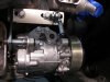
Greig, here are some pic's of how we addressed the compressor bracket issue.
We made a backing plate for the bracket, allowing it to sit flush with block without using a bunch of Mickey Mouse washers/spacers.
We also had to fabricate a bracket to mount to position “A” on front of the compressor This bracket allowed an attachment point for the belt tension Heim.
Jim
Attachments
Craig Sinasac
Supporter
Very nice Jim, thx.
Cheers,
Craig
Cheers,
Craig
I have a few things going on. Got the front and rear end torqued, with a few exceptions. I am having my coolant pipes extended, and a shroud made for the radiator. I just got my footwell hard lines in the mail. I would like to install them tomorrow, but I am not sure if have all I need?

Here are the hard lines I received Friday. The photos I see in the build manual and in other builds shows a long line going from the "T" across the center frame to the right side footwell. I also don't find what I assume is the pressure valve that activates the brake light? Do I have all I need?
BTW- while I work on the brake system, I was wondering if it is common for builders to include a brake bias control? It appears the foot pedal system can easily have that option.
I am also going to make a metal tab that supports the brake line at this connection area. It appears the the fitting was designed for that. Thoughts?
The other parts are in the mail! Thanks Dean… :thumbsup:
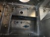
Made a little progress. Don pressure tested the fuel tank. It held 1 psi for several hours. After returning a few days later, it had leaked down. Probably the fitting. I also got rubber padding laid on the frame and Boom Matt on the side of the frame next to the fuel tank. I also mocked up where mounting tabs will go on the tank for mounting to the frame. It goes to the fabricator tomorrow.

I also mocked up a template for fabrication on a bulkhead to enclose the fuel tank area. I am going to have an access door located for access from the engine bay into the fuel pump area next to the fuel tank. I cannot have an access panel from inside the passenger area as I have the new interior tub that doesn't permit access from there.

I also got the brake lines placed. I have a question….
Here is a "T" in the footwell area. It has a tab on top. Is that to serve as a standoff so the lines are not against the footwell, or is it supposed to go into a hole that it made in the footwell?

I also mocked up a template for fabrication on a bulkhead to enclose the fuel tank area. I am going to have an access door located for access from the engine bay into the fuel pump area next to the fuel tank. I cannot have an access panel from inside the passenger area as I have the new interior tub that doesn't permit access from there.
I also got the brake lines placed. I have a question….
Here is a "T" in the footwell area. It has a tab on top. Is that to serve as a standoff so the lines are not against the footwell, or is it supposed to go into a hole that it made in the footwell?
Howard Jones
Supporter
The idea is that the little tab would fit into a hole thus preventing the bracket from rotating when the hold down fastener is tightened. I would just saw it off. Then I would drill and tap the mounting hole so that there isn't a need to access the back side to hold a nut as the bolt is tightened. 1/4 20 will do nicely.
I forgot to ask…
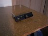
There are 2 pressure relief valves. Can someone clarify which goes on the single hard line and which goes on the lines that come off the "T"?
There are 2 pressure relief valves. Can someone clarify which goes on the single hard line and which goes on the lines that come off the "T"?
Make a small 90 degree bracket to hold the hard brake lines at the rear of the chassis. This relieves stress on the hard lines as the suspension moves.
Mine are labeled "1" pound and "2" pound. That is why I wondered if they had a specific location. They are physically the same size.
The blue valves are ALWAYS 2 lbs....red ones are 10lb...
There is no such thing as a 1lb residual valve in general circulation
There is no such thing as a 1lb residual valve in general circulation
A swear I sometimes think I am losing my mind! I looked at the residual pressure relief valves…. I thought I saw a 1 # and 2 #. I went back and finished the brake lines. Guess what? Only 2 #ers. And I don't drink either. Maybe I need to start!
You can probably tell I am a rookie at this. Thus the questions that may seem obvious to others. I had asked Fran via email if there is a preference to the reservoir location for the brake/clutch fluid. I have the Tilton resevoir that I will use. What I meant was to ask Fran… is there a preference for the pistons location that are just behind the pedals? If they are mounted outside the footwell, the rods from the pedals to the pistons would have to be extended. Then, as force is applied to the pedals, this force would transfer to the wall the pistons are mounted on resulting in possible movement of that wall?? More leg room, but maybe not as stable… I think. That is what I was trying to ask Fran. Is more leg room needed?
I received the 90 and 45 degree extensions for the coolant pipes. Thanks Craig!
And last… my son Tyler finished his season on the Pro Tour. SuperNats had big time rain in Vegas. He had a great race and has already signed for next year.

So… he got a call today from the race director for his March race- The Lone Star Grand Prix. They wanted to know if I would bring the SLC for the pace car. March completion???? Not so much. Oh well- maybe 2015.
I am having fun with the build!
You can probably tell I am a rookie at this. Thus the questions that may seem obvious to others. I had asked Fran via email if there is a preference to the reservoir location for the brake/clutch fluid. I have the Tilton resevoir that I will use. What I meant was to ask Fran… is there a preference for the pistons location that are just behind the pedals? If they are mounted outside the footwell, the rods from the pedals to the pistons would have to be extended. Then, as force is applied to the pedals, this force would transfer to the wall the pistons are mounted on resulting in possible movement of that wall?? More leg room, but maybe not as stable… I think. That is what I was trying to ask Fran. Is more leg room needed?
I received the 90 and 45 degree extensions for the coolant pipes. Thanks Craig!
And last… my son Tyler finished his season on the Pro Tour. SuperNats had big time rain in Vegas. He had a great race and has already signed for next year.
So… he got a call today from the race director for his March race- The Lone Star Grand Prix. They wanted to know if I would bring the SLC for the pace car. March completion???? Not so much. Oh well- maybe 2015.
I am having fun with the build!
Mike, there is a no cost extended footbox option when we are building the chassis..but it does require the customer to make a couple of brake lines.
Unless you have a leg like Arnold you are not likely to bend a 1/4 inch thick bulkhead...if you use pushrods then you cannot use the adjustable pedal mount
Unless you have a leg like Arnold you are not likely to bend a 1/4 inch thick bulkhead...if you use pushrods then you cannot use the adjustable pedal mount
Don got the adjustable pedal assembly together. We reversed the pin behind the pedals so it doesn't interfere with my heel. The wing nuts were changed to locking nuts that are not completely tight. Now the assembly can be moved without needing a wrench. I did not want to go to that trouble for the few times my wife or someone else needs to change pedal position.

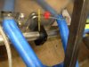
Added some insulation on the frame before the coolant pipes are welded/installed. I will have 90 degree and 45 degree elbows welded to my pipes, and then use Summit flexible SS tubing.

I am not sure about the needed clearance for the front wheels where the coolant pipes go into the trunk area. The tube positions perfectly into this hanger…. but, will that present any clearance problem with the car in full dress? :shrug:


Added some insulation on the frame before the coolant pipes are welded/installed. I will have 90 degree and 45 degree elbows welded to my pipes, and then use Summit flexible SS tubing.
I am not sure about the needed clearance for the front wheels where the coolant pipes go into the trunk area. The tube positions perfectly into this hanger…. but, will that present any clearance problem with the car in full dress? :shrug:
Mike
You will be fine with your positioning....
You will be fine with your positioning....
Do most builders insulate the pipes forward to the cabin (in the area where the tire is)? I have not seen many builders photos that indicate that. While it would protect the pipes, if they were uncovered in that area, they could cool better. Thoughts?

I'd insulate this point with high temp rubber, exhaust wrap or something to stop abrasion. I wouldn't worry about the cooling aspect of wrapping or not in this area - the radiator and fans should tackle that. Wrapping the pipe within the rocker area may help with heat infiltration into the interior cab
Attachments
Similar threads
- Replies
- 14
- Views
- 2K