G50 Competition Transaxle Support

Randy V

Moderator-Admin
Staff member
Admin
Lifetime Supporter
Hi Guys,

Since my car will see track use and performance driving instruction - I decided that I would like to see some additional support to the transaxle over the 4 - 10mm studs that are used to mount the transaxle.
For normal or spirited driving, this type of support would most likely be overkill - but true to form - I over engineer everything..

Below are a couple of pictures to give you an idea of the mounting system.

The struts are 13" long 3/8" Swedge tubes with Rod-Ends (Heims) at either end.
The main bracket is made from 3/16" thick mild steel.
The lower heim brackets made from 1/8" mild steel.
The upper brackets were purchased from RCR - They are the angle clevis' used on the RCR40 Lower control arms.

If you visit my website:
http://www.GT-Forty.com

and then click on the link to the Competition Trans Support

You can see the steps I went through to create this support system.
From most everything I've seen of the various manufacturers - this mounting system should be able to be used in most manufacturers cars.

Here's a direct link to the page;
GT-FORTY.COM

IMG_1097.jpg


IMG_1110.jpg


IMG_1104.jpg


Lots more pictures on the website.. I hope they help someone out there..
 
Hi Randy
Great idea.
Since i have my G50 in the workshop i think about how to support it a little more, than just hanging it on the original 4 bolts to the transadapterplate.
In my concepts i always tried to think of something which keeps the whole trans/engine-unit somehow elastic mounted in order to keep stress loads and noicetransfer away from the chassis.
First thing i noticed, is the RCR transadaptermount to the chassis. This si not realy a elastic connection. I don´t realy understand the purpose of the nylonbushing, because if you tie it down against your distance ( your wider one, or in the original position to the chassis crossmember) it is a fixed connection. A solution would be to have two of this nylon bushings , mounting agains the adaptorplate from front and back and the bolt going through them with enough nylon material between it and the adaptorplate. this way it would be somehow eslastic ( at least in the same way as the ZF´s are mounted).
I thought about using two elastich transmission mounting joints ( instead of your u-bent sheet metal there) for the rear support as well, connecting this the same way with adjustabel rod end struts to the chassis as you did it, would also keept this connection flexible enough.
Just my thoughts for which you delivered an excellent base.

What do you think ?
Why do you want to keep your transengine-combo from moving a little within elastic mounting points ( i think the fixed solution will put more load to the transmissionhousing than an elastic solution) ?

There is a saying in germany.
It is always easier to close the door, after the pig already left the stable.
Keep on your great work. I can not mention often enough how helpful your buildsite is.
Thanks
TOM
 

Randy V

Moderator-Admin
Staff member
Admin
Lifetime Supporter
In my concepts i always tried to think of something which keeps the whole trans/engine-unit somehow elastic mounted in order to keep stress loads and noicetransfer away from the chassis.
First thing i noticed, is the RCR transadaptermount to the chassis. This si not realy a elastic connection. I don´t realy understand the purpose of the nylonbushing, because if you tie it down against your distance ( your wider one, or in the original position to the chassis crossmember) it is a fixed connection. A solution would be to have two of this nylon bushings , mounting agains the adaptorplate from front and back and the bolt going through them with enough nylon material between it and the adaptorplate. this way it would be somehow eslastic ( at least in the same way as the ZF´s are mounted).

Hi Tom.. I'm not sure why the nylon bushings either - Fran will have to answer that question. The motor mounts are polyurethane so there is a little compliance there - but - that compliance is pretty well negated by the block adapter being mounted solidly. I'm also going to be adding additional rear support mounts for the block adapter rather than having the adapter spaced out over 2.5 inches from it's mounting point at the rear chassis horseshoe. So all this said - the engine and transaxle will be for all intents and purposes - solidly mounted.

I thought about using two elastich transmission mounting joints ( instead of your u-bent sheet metal there) for the rear support as well, connecting this the same way with adjustabel rod end struts to the chassis as you did it, would also keept this connection flexible enough.
Just my thoughts for which you delivered an excellent base.

It's a good thought Tom. I'll admit that I hadn't thought of that..

What do you think ?
Why do you want to keep your transengine-combo from moving a little within elastic mounting points ( i think the fixed solution will put more load to the transmissionhousing than an elastic solution) ?

Since this car will be used in a competition oriented setting - I'm not overly concerned about having the driveline mounted solidly. The one "Good" thing about the side-mounts being poly is that it will dampen some of the drumming that would occur from solid mounts going to the sides of the alloy tub..

There is a saying in germany.
It is always easier to close the door, after the pig already left the stable.
Keep on your great work. I can not mention often enough how helpful your buildsite is.
Thanks
TOM

Thanks Tom - I appreciate the kind words and your feedback on my project. I will be looking over the mounts again to see how I could make them more compliant..
 

Ron Earp

Admin
Randy, have you made some half shafts up yet? I'm curious to see how yours come out as you chassis setup/position seem similar to mine. I like the work with the mount. It is fairly simple and could be duplicated with off the shelf parts from Pegasus, except for the attachment to the box and that looks like a simple weld a bracket on job. Maybe you should turn this into a "How To" article and send it to Lynn Miner. He could use more to beef up the section, especially on non-SPF technical articles.
 

Randy V

Moderator-Admin
Staff member
Admin
Lifetime Supporter
Hi Ron,

Fran's got new axles on the way so I'm holding off from making my own since I've got a lot of other fish to fry with this car..

Thanks for the kudos on the support system.. I'll contact Lynn offline and see what he says. With the exception of the bracket itself - most everything can be purchased from Fran (angle clevis') and speedway motors..

I made a tracing of the bracket and will scan it in (once I get my scanner hooked up again) and make the template available as well..
 

Chris Duncan

Supporter
Randy,

Please don't take this personally but I'd like to critique your bracket if you don't mind. I've been lurking on this thread but can't bite my tongue any longer. I totally agree with your general idea of more than one mount point, just want to point out some other things to improve what you've started.

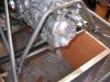
First thing though would be to address the way a G50 should be mounted. It was designed to be mounted in at least 2 places, anyone that is using the 4 bell housing bolts alone is asking for trouble. Just look at the bell housing with it's swiss cheese of holes and it's easy to see it needs more mount points.

In addition it is also a problem if you have some mounts that are rigid and some that are flexible. Make them either all rigid or all flexible. If you mix rigid and flexible all the load under certain instances will go to the rigid mount. Vibration fatigue will also be concentrated on the rigid mount.

Let's start with the thickness of the materials you've chosen. Look at one of the original cars if you ever get a chance. All the brackets on the chassis are made from the same or nearly the same gauge as the chassis itself. Just guessing but it's probably about 18 or 20 gauge sheet. That's max .050" or less that 1/16" thick. Granted most of these brackets are flanged and have doubling washers at the holes. But this gives you a starting point on what thickness is necessary.

The washer doubling at the hole brings the thickness (only at the hole) to about 1/8" so if the entire bracket is 1/8" then it's overkill but acceptable for our purposes because flanging and doubling is very labor intensive. So if you follow the intent of the original car then no steel bracket anywhere on a GT40 replica should be over 1/8" thick. If it becomes necessary to go past that then it's likely to be compensating for less than optimum design.

One other point before going to the design aspect. Please don't trust the home builders for steel supply unless they can guarantee the alloy of the steel . 1018/1020 is a minimum. Look for a local metals supplier or go with the likes of McMaster Carr. There's bed frame angle iron alloys out there that are inadequate for anything approaching a racing application. This goes for graded bolts also. The Chinese suppliers to the home builders are notorious for fudging the actual grades.

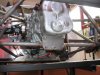
Once we've decided that 1/8" is adequate thickness let's look at the other dimensions. I have a general rule of thumb for a bolt hole bracket loaded in double sheer. The distance from the edge of the hole to the outer edge of the bracket should be equal to the diameter of the hole. The shape of the edge should be a radius with the centerpoint common with the bolt hole. The base of the bracket can be wider so as to form a rigid triangular shape. So to refine your existing 1/8" bracket without starting from scratch just round off the 90deg outer corners. They are just adding weight without adding any additional strength. While your at it do the same to the rear of the trans case, the 90deg outer corners where the rear of the trans was cut off could be rounded to shave weight.

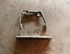
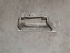
typical 1/8" thick bracket

file.php


typical original GT40 1/16" thick flanged/doubled bracket, an example of why these cars weighed very close to 2,000 lbs., this bracket takes about twice as long to fab as a flat 1/8" piece.

file.php


The main part of your bracket could be treated in a similar manner, round off the sharp outer corners. This area of the trans case where it bolts together is very rigid, you don't need to add any additional strength. The only strength you need is whatever is adequate to transfer the force from the case bolts to the rod end bolts. So think about how much load the one rod end bolt on each side will hold. That's all the load you need to transfer to the case. You could probably could get by with bracketing off just 2 of the case bolts on each side. 3 on each side is somewhat overkill but if you didn't want to start from scratch then at least remove the piece that connects the bottom 2 case bolts. It's adding only weight and no strength.

If you wanted to start from scratch you could go with 1/8" plate bracketing off just 2 case bolts on each side. This would mean you would have to locate your double sheer rod end bolt tabs as close to the case bolts as possible and still have room for the socket/wrench.

Another thing you could do if you didn't want to start from scratch is just swiss cheese your existing bracket. 1/2" holes, spaced no closer than the diameter distance of your rod end bolt hole from any edge, and 1/2" from each other. This is one method to reduce the weight to what a 1/8" thick bracket would be and in some loading situations it would be stronger.

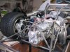
I applied these methods and others like them to get my car to 2200 lbs. (wet) Considering the original cars were around 2000 lbs for the MK1 this is going in the right direction if you really want to call it a race car.
 
BF,

Since you plan on track time, you may want to consult with some of the DRB guys.
Their years of G50 experience have led to the development of extra support bars(to help control torque flex), in addition to the typical front studs/rear chassis mount. Apparently, in some high horsepower applications, there have been some issues that these extra bars have addressed. Perhaps they will chime in.


Bill
 
Randy,

Considering the original cars were around 2000 lbs for the MK1 this is going in the right direction if you really want to call it a race car.

According to "the ford that beats ferrari"(page 89 and pages 424 ff) the original GT40 where pretty heavy cars. With a typical MKII wet weight of 2704 lb and a typical GT40 MKI @ 2438 lb. Following that, the possibly lightest GT40 where the roadster types with a mere 2350lb.

Other than that your engineering reasoning makes totally sense.

Thanks
TOM
 
When I got my 930 trans, the mechanic sent this mounting along with the trans. I don't know if it is a stock porsche setup or not. It is an aluminum unit and is basicly the same type of mount as Bigfoots. If it is stock, then the factory units were pretty rigid. I have built my own setup for my DRB and I think it is strong enough to hold the trans in place. It would seem that if the interest is being light weight, an aluminum mount might be in order.

Bill
 

Attachments

  • Web P1010009.jpg
    Web P1010009.jpg
    87.8 KB · Views: 419
  • Web P1010007.jpg
    Web P1010007.jpg
    78.5 KB · Views: 418

Chris Duncan

Supporter
According to "the ford that beats ferrari"(page 89 and pages 424 ff) the original GT40 where pretty heavy cars. With a typical MKII wet weight of 2704 lb and a typical GT40 MKI @ 2438 lb. Following that, the possibly lightest GT40 where the roadster types with a mere 2350lb.


I defer to Ronnie Spain who puts the MK1 at 2000. I think you're looking at a MK1 wet weight of 2438 and that's with 40 gallons of fuel @ 8lbs per. or 320 lbs. So that puts it a 2120 with no fuel, so 2000 might be no oils or coolant.

My car weighs 2170lbs. with 3 gallons of fuel and full oils and coolant.
 
Last edited by a moderator:
I defer to Ronnie Spain who puts the MK1 at 2000. I think you're looking at a MK1 wet weight of 2438 and that's with 40 gallons of fuel @ 8lbs per. or 320 lbs. So that puts it a 2120 with no fuel, so 2000 might be no oils or coolant.

My car weighs 2170lbs. with 3 gallons of fuel and full oils and coolant.

Its a pitty that our cars need all of that to drive them :D:D:D

I´m also a fan of the the lightweight approach, my friends are always teasing me by saying one day your bike will ride on top of you because it is much lighter than you ( i´m 74 kg).

But just another thought on the load towards the transmission mounting flange.
I wondered about the way the G50 s (for example a 03/04/05/50/52 in a 964) are originaly mounted ? The transaxle at one point at the very end. And that aircooled flat six is mounted also at one point on the very other end. There is no support in between!
So having to take the moments from the transaxleweight plus the engineweight in the original configuration, i guess the flange could hold all the load when it just has to support the transaxle weight itself.
 
Last edited:

Randy V

Moderator-Admin
Staff member
Admin
Lifetime Supporter
Kalun - Thanks for your Critique of my fabrication. I had originally intended on having 3 sets of holes in the brackets in a vertical plane which is why I created them the way I did. I could well trim them down but may not.
In terms of the quality of the steel I used - I've bought this "lumber yard" steel before and found it to be of relatively high quality with very little impurity - noted as slag or other chaf from the welding process. In terms of looking for specific alloys for a bracket that is quite easily over-engineered for the task - I was not concerned.
So - this may make me some sort of hack - but I'm a hack that's been doing it for a lot of years and so far my creations hold together quite well. Perhaps I've just been lucky! :)
A racecar it is not. It only looks like one. The Track use that this car will get will be limited to something well shy of 10:10's work as it will be for instructional use.

Bill - Thanks for including pics of your 930 mount! It's good to know that I'm not the first to use the end-cap studs to support the weight of the transmission by an external bracket!

Hopefully more DRB guys will see fit to contribute to this thread..

Thanks all...

--edit--
BTW - Have you ever tried to drill through that Bedframe Angle iron? It's tough as HECK!!!! ;)
 
It is of our opinion that a transaxle like the Porsche G50, 930 or later GT spec. units that are setup inverted in a mid-engine type application should have some form of rear tail mount. We usually reccomend a rubber mount for street or hard delrin for track use. It is important to support the gearbox in high load situations to minimize deflection and decrease the wear. Porsche never intended these units to be run without end support, however it has and can be done, does not meen it isreccomended. I nice step in the right direction fellows, keep it up and your gearbox will last longer and minimze the chance of the case becoming damaged, or breaking it all together.

Take care gents,
 

Chris Duncan

Supporter
I would like to slightly modify my position after talking to an engineer friend of mine to say that 2 sets of mounts should be sufficient for an engine/transaxle setup. When I think about all the longitudinal engine/trans setups I've ever seen have one pair of mounts for the engine and one pair of mounts for the trans.

So some manufactures have moved Porsche transaxle mounts from the tail end to the bell housing area. This shouldn't really be much different in terms of loading when you look at moment arms etc.
 
und hier die fotos
 

Attachments

  • IMG_1445.jpg
    IMG_1445.jpg
    44.6 KB · Views: 342
  • IMG_1447.jpg
    IMG_1447.jpg
    45.2 KB · Views: 332
  • IMG_1456.jpg
    IMG_1456.jpg
    53.9 KB · Views: 362
I should say a bit more directly that these gearboxes were not to be designed as stressed members of a chassis. Designs like Fran's Superlite and GT's, incorporate a rear subframe and suspension mounting system to translate load, and do an excellent job of keeping the rear end from flexing. This kind of a system that minimizes the axle side load and keeps the gearbox free from stress works well.

Making a mount for the tail is good insurance, but there is no substitute for fine engineering. The later 6 speed GT2/3 units, are extremely heavy and require a mount for the tail. I have had experience with a manufacturer using the GT2/3 series of gearbox and tail-mounting of these units is imperative due to their length and weight.
 

Randy V

Moderator-Admin
Staff member
Admin
Lifetime Supporter
Olf59 - The G50/50 - 01 have the mounts like yours and a great place to tie in. On my G50/03 (modified housing - see my build site) I no longer had the large mount so I needed to make something else that would suffice.

Ryan - Thanks for the input! I don't know how good of a job my mount will do, but I feel confident that it will certainly be better than nothing at all and should cause no harm...
 
Back
Top