Hey just a word of advice I wish I had known. Now that my car is nearly fully put together and AC working. I get a ton of cold air that back flows from the evaporator unit onto my girls feet. I suspect I didn’t make big enough holes in the aluminum chassis and plastic housing. I made holes just like you did, and it seems everyone else does. Just a thought, be curious what others think.

You are using an out of date browser. It may not display this or other websites correctly.
You should upgrade or use an alternative browser.
You should upgrade or use an alternative browser.
Geoff's Build Thread
- Thread starter zensation
- Start date
Hey just a word of advice I wish I had known. Now that my car is nearly fully put together and AC working. I get a ton of cold air that back flows from the evaporator unit onto my girls feet. I suspect I didn’t make big enough holes in the aluminum chassis and plastic housing. I made holes just like you did, and it seems everyone else does. Just a thought, be curious what others think.
That's super helpful thanks for the info. So the air is "back flowing out of the blower motor because of too much flow resistance at the drilled holes? I'll definitely test out in gocart pre body and see what I can find. Might have to make some sort of deflector or even an air box with. Filter on it to add some intake restriction or something. Thanks for the heads up.
It could even be the duct I designed for under the dash. I’m not an engineer. I did the same holes you did and then created a custom duct that encompasses all the holes and then goes into each 2.5in flex duct for the vents. Truth be told the restriction could be there. It even could be that the fan is more powerful than flow across the coil allows. I’m not too sure. Like you said I’d test it in situ before you close it all up and see if you experience the same I am. Needless to say she’s not too happy riding in the car anyways, much less freezing feet.
It could even be the duct I designed for under the dash. I’m not an engineer. I did the same holes you did and then created a custom duct that encompasses all the holes and then goes into each 2.5in flex duct for the vents. Truth be told the restriction could be there. It even could be that the fan is more powerful than flow across the coil allows. I’m not too sure. Like you said I’d test it in situ before you close it all up and see if you experience the same I am. Needless to say she’s not too happy riding in the car anyways, much less freezing feet.
Lol I heard that
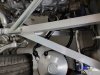
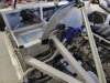
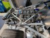
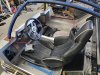
I reached my first milestone this week, plumbing complete! Clutch bled, brakes bled, fuel lines, oil lines, coolant lines, hvac and heater lines. I hard lined what i could and used an fittings on everything. feels really good.
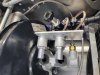
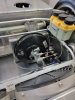
the other thing i've been working on is tracking a leak from the mini cooper brake master cylinder reservoir, I had originally used some 1/2 inch aluminum tube to make some leg extensions for the factory mini cooper reservoir that would allow me to reverse the reservoir(since it sits at an angle on the mini cooper firewall) which when reversed it sits flat. I never really liked this solution and it had been leaking so i welded together my own reservoir. Well that one leaked at the back grommet as well in the same place, so i figured it must be the rubber grommet. but to kill 2 bird i decided to try and find a remote reservoir solution and i cross referenced a ton of parts and finally found a 2002 BMW OEM grommet and hose barb solution that works perfectly for the mini cooper master which for anyone else wanting to run this setup that will be the easiest rout to take so big score there. What is required is 2 BMW grommets (part # 34311121911) and 2 of the remote hose barbs (part # 34321102282). I purchased both from Pelican Parts. I thought I would share in case anyone wants an extremely simple solution for Brake booster setup using the 2010 mini cooper parts. Enjoy the pics!
the other thing i've been working on is tracking a leak from the mini cooper brake master cylinder reservoir, I had originally used some 1/2 inch aluminum tube to make some leg extensions for the factory mini cooper reservoir that would allow me to reverse the reservoir(since it sits at an angle on the mini cooper firewall) which when reversed it sits flat. I never really liked this solution and it had been leaking so i welded together my own reservoir. Well that one leaked at the back grommet as well in the same place, so i figured it must be the rubber grommet. but to kill 2 bird i decided to try and find a remote reservoir solution and i cross referenced a ton of parts and finally found a 2002 BMW OEM grommet and hose barb solution that works perfectly for the mini cooper master which for anyone else wanting to run this setup that will be the easiest rout to take so big score there. What is required is 2 BMW grommets (part # 34311121911) and 2 of the remote hose barbs (part # 34321102282). I purchased both from Pelican Parts. I thought I would share in case anyone wants an extremely simple solution for Brake booster setup using the 2010 mini cooper parts. Enjoy the pics!
Attachments
Ken Roberts
Supporter
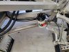
I thought you were plumbing the complete brake system in braided hose? Are my eyes deceiving me because it looks like copper/nickel.
Last edited:
Thanks for keeping up on my buildI thought you were plumbing the complete brake system in braided hose? Are my eyes deceiving me because it looks like copper/nickel.
After doing the fronts which took about 12 feet of the braided I had leftover, there wasn't enough left to run to the back. Advance had copper in stock so it was easier. 0 concerns of the famous internet timer of expansion, given the material expansion rates which I can find tabulated in my engineering books if you like. besides if there was any truth to your claims with the amount I used up front alone I'd have a spongy pedal bit it's rock solid. Just goes to show don't believe everything you read on the internet right?I thought you were plumbing the complete brake system in braided hose? Are my eyes deceiving me because it looks like copper/nickel.
")
Ken Roberts
Supporter
Did your engineering books tell you its’s not DOT compliant? 
Did your engineering books tell you that the lines you made up yourself must be built by a company that is certified to make braided hoses for DOT use?
If it’s a car you just plan to drive on a race track than have at it but if you plan to drive it on public roads then it’s our concern as well.
Did your engineering books tell you that the lines you made up yourself must be built by a company that is certified to make braided hoses for DOT use?
If it’s a car you just plan to drive on a race track than have at it but if you plan to drive it on public roads then it’s our concern as well.
Did your engineering books tell you its’s not DOT compliant?
Did your engineering books tell you that the lines you made up yourself must be done by a company that is certified to make braided hoses for DOT use?
If it’s a car you just plan to drive on a race track than have at it but if you plan to drive it on public roads then it’s our concern as well.
Once again in most states that is not the case. It sounds like in your case your state has mandated something and you are assuming it's that way everywhere. If my state required it I would certainly do things differently. I don't really want to argue about it anymore. This works and that's really all that matters.
Ken Roberts
Supporter
DOT compliance is a federal mandate. Your State may not enforce it. It doesn’t mean you are free and clear. The car should be built to both Federal and State laws.
You seem to have an issue with me so I will refrain from further comments on your build log. Cheers!
You seem to have an issue with me so I will refrain from further comments on your build log. Cheers!
Last edited:
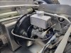
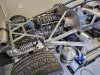
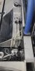
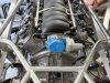
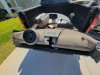
Custom headers came in yesterday. I had these made for a turbo application and they will make it extremely easy to rout the exhaust straight out the back! Then later I can replace my muffler section with 2 top mount turbos.
Attachments
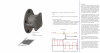
Starting to plan out my vehicle speed sensor solution and as Im coming off a couple of projects with my custom vehicle electronics business, i just had a very relevant project cross my desk. For some backgrounds I develop circuitry for converting signals, processing, and modding automotive applications. A couple times I have had to convert peoples older VR signaling to digital for various reasons either a new ecu sending a speed signal to an older speedometer and interpretting that signal, or in the most recent case a new digital dash conversion bypassing the factory speed signal processing to an aftermarket ecu.
Well that got me thinking about how im going to be reading the speed on the SLC and How id like to have input to the GM PCM. Knowing the GM PCM uses a 2 wire VR sensor typically in the transmission and sees around 4000 pulses per mile, I have come up with a way to get that speed from the front wheel speed. And the best part is ill definitely spend under $100 more than likely itll cost around $20. Im going to use a 3 wire proximity sensor and very simply read pulses off the backs of the lug bolts on the SLC/ corvette wheel hub which protrude about 1/8inch. The prox switch will have about a 1.5mmsensing distance. I did a write up on how this can be very simply accomplished for anyone with any PCM that is looking for a VR speed signal.
Well that got me thinking about how im going to be reading the speed on the SLC and How id like to have input to the GM PCM. Knowing the GM PCM uses a 2 wire VR sensor typically in the transmission and sees around 4000 pulses per mile, I have come up with a way to get that speed from the front wheel speed. And the best part is ill definitely spend under $100 more than likely itll cost around $20. Im going to use a 3 wire proximity sensor and very simply read pulses off the backs of the lug bolts on the SLC/ corvette wheel hub which protrude about 1/8inch. The prox switch will have about a 1.5mmsensing distance. I did a write up on how this can be very simply accomplished for anyone with any PCM that is looking for a VR speed signal.
Attachments
Are you using the VSS on the front hubs for ABS? If you are simply looking for vehicle speed, bolting a tone ring between the drive axle CV and the gearbox flange is a proven, easy option. Use the GM sensor from the GM transmission, mounted externally adjacent to the ring. GM PCM loves it.
Are you using the VSS on the front hubs for ABS? If you are simply looking for vehicle speed, bolting a tone ring between the drive axle CV and the gearbox flange is a proven, easy option. Use the GM sensor from the GM transmission, mounted externally adjacent to the ring. GM PCM loves it.
I'm using purely for VSS for the ECU to send the speed to gauges, and potentially for the Epas system. 5 pickups just won't be enough resolution for something like ABS or traction control which is where a tone ring would shine. For VSS I just have a problem with using a drive axle in general due to wheel slip. The only option for me is a mothod of reading off a front hub. I also have designed a tone ring with 47 teeth to go on the back of the hub which I may toy around with as well.
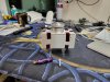
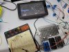
I wanted to update this thread with some info for those looking to use a purely digital dash and getting all sensor data from the GM ECM. Specifically an e67 ecm. for wiring simplicity reasons I am using a completely digital dash on my build, but one thing i ran into was getting the fuel level for the dash. Luckily the e67 ecm has primary and secondary fuel level signal pins on the blue connector so i looked to tie into that, however i didnt know if the centroid sender would play nice with the ecm. so I set everything up on the bench and did some testing with the sender, the ecm, and the dash.
the centroid sender sends a 0ohm when full/100 ohm empty signal
the ecm calibration is set to something like 40 ohm full/250 ohm empty signal(I am assuming you can use HP tuner software to change that calibration)
What i was able to get working on the bench was using a 250 ohm pullup resistor to 5v and tieing the centroid sender signal wire directly to the primary and secondary fuel level pins in the ecm. The ecm averages out the 2 signals to create the fuel level which is sent to the dash via can bus. I then tested various resistors up to 100ohms to get some calibration points for double checking before connecting the centroid sender. With the centroid sender connected it now shows 0% fuel outside the tank which is correct. ill just add the pins to the ecm connector and run them directly to the sender in my gmpp harness done and done.
Attachments
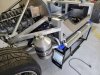
A few updates this week. I was able to get in my digital dash and begin bench programming on the as indicated in my previous post and ive attached a few more pictures of that.......
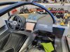
But the big update revolves around my dash. I was able to find a Koenigsegg dash out of one of the movie Koenigsegg cars from the Need for Speed movie at a guys shop in florida that has the chassis. He didnt need the interior so i got it all off him for the exorbitant price of $500 lol I got it back home and began cutting it to fit and it looks like its just going to fit awesome with the slight modifications i made! I just need to glass it back together after narrowing it a bit. This is perfect for me since i was planning on ditching my previously modified dash anyways! I love the new look!
But the big update revolves around my dash. I was able to find a Koenigsegg dash out of one of the movie Koenigsegg cars from the Need for Speed movie at a guys shop in florida that has the chassis. He didnt need the interior so i got it all off him for the exorbitant price of $500 lol I got it back home and began cutting it to fit and it looks like its just going to fit awesome with the slight modifications i made! I just need to glass it back together after narrowing it a bit. This is perfect for me since i was planning on ditching my previously modified dash anyways! I love the new look!
Attachments


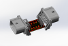
the other thing im going to be doing is making a an 8 channel IO inverter for the Raptor pro system to make it seemlessly function with the infinity box system. The infinity box requires gound signal inputs to the master cell while the raptor system sends 5v or 12v outputs. I designed the circuit under the umbrella of myu electronics business already so i just need to manufacture some samples and well be good to go. Its roughle a 2" x2" module that will splice directly in line to the raptor receiver harness and the infinity box harness. with sealed automotive grade connectors. it will feed the 12v and ground directly through to the raptor receiver. This is way more space efficient than a 12" square relay panel which is the other option.
Attachments
Similar threads
- Replies
- 14
- Views
- 2K
- Replies
- 1
- Views
- 2K
- Replies
- 21
- Views
- 2K