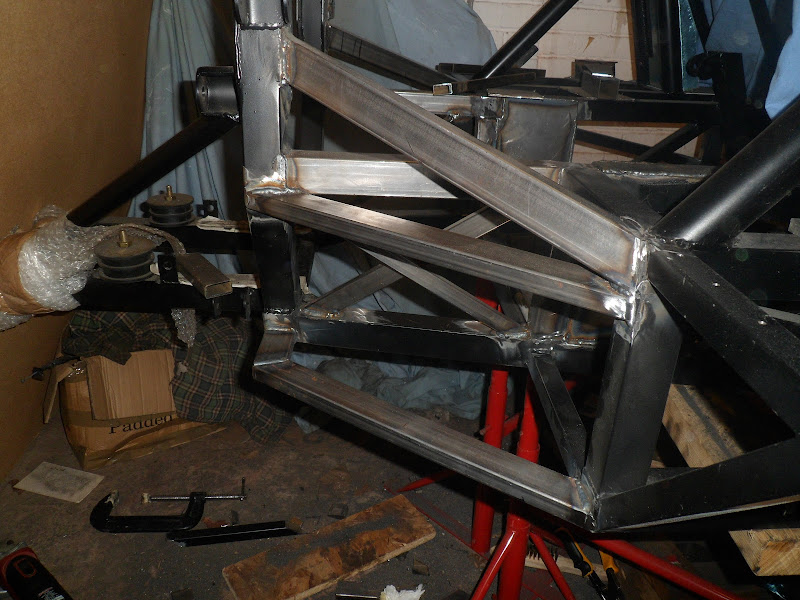
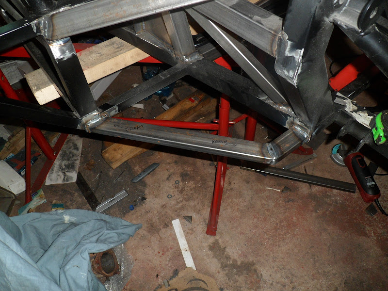
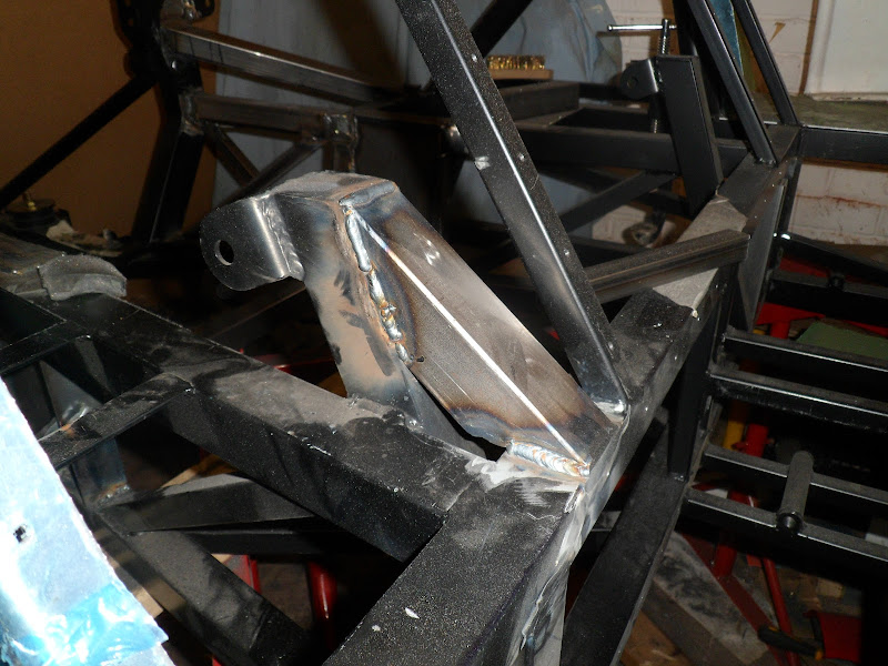
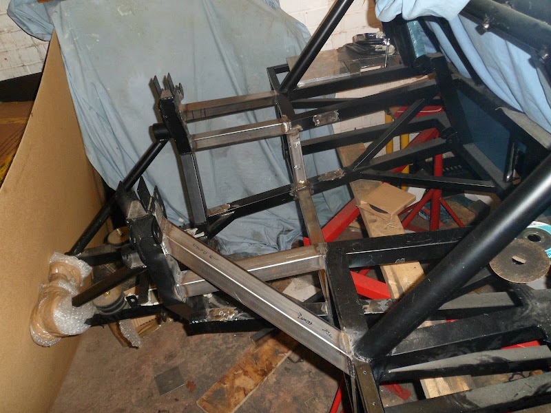
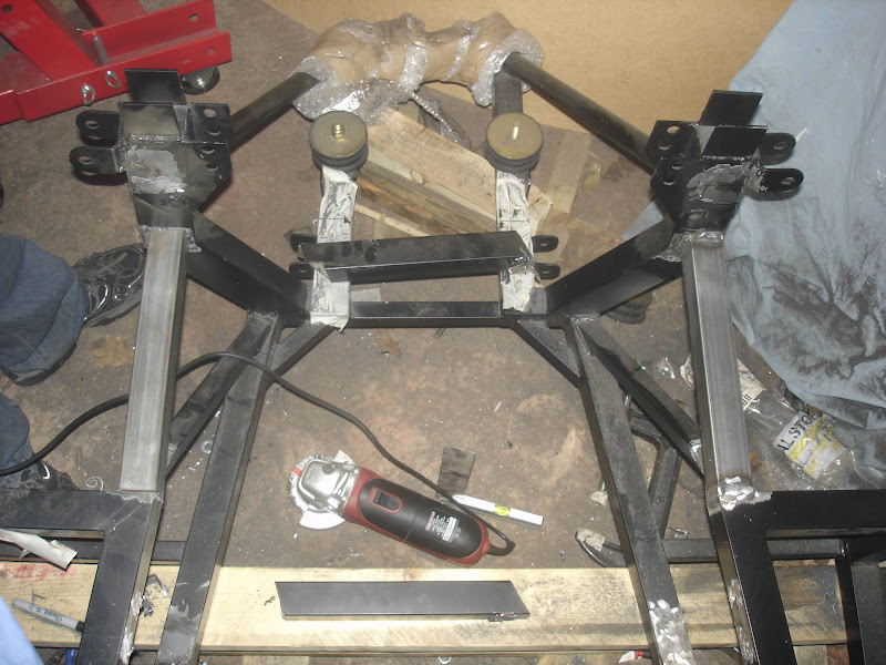
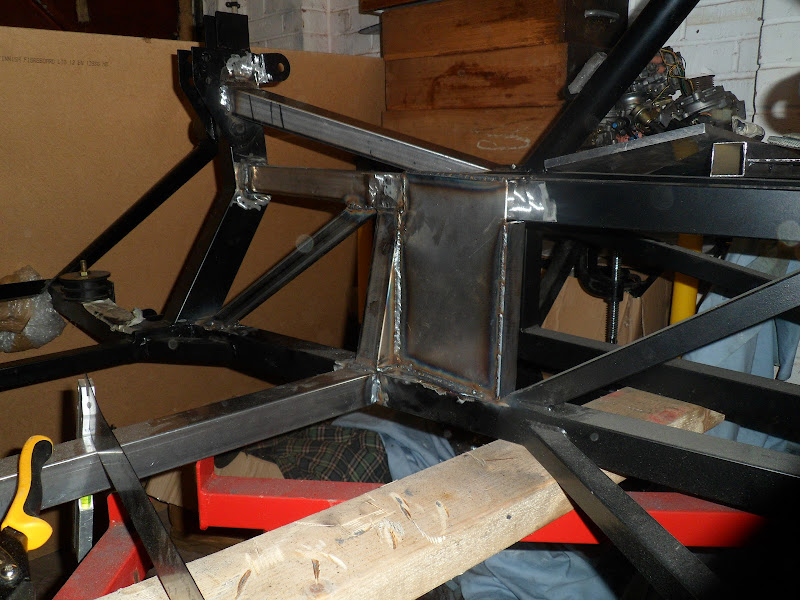
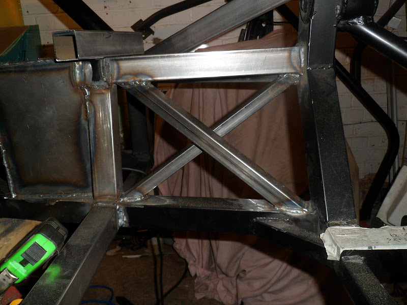
Stuck the engine back in and changed my mind on the frame side of the mounting backets.
Basically it er doesn't fit in with them in place! =8-o
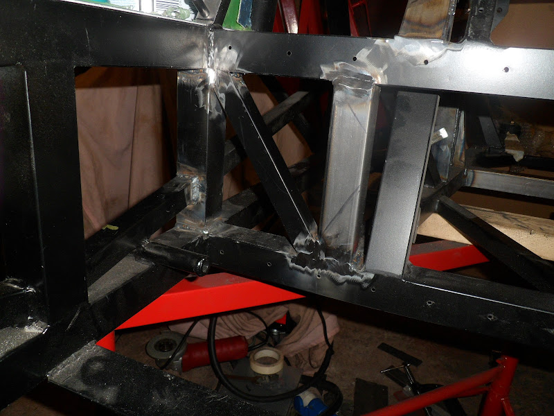
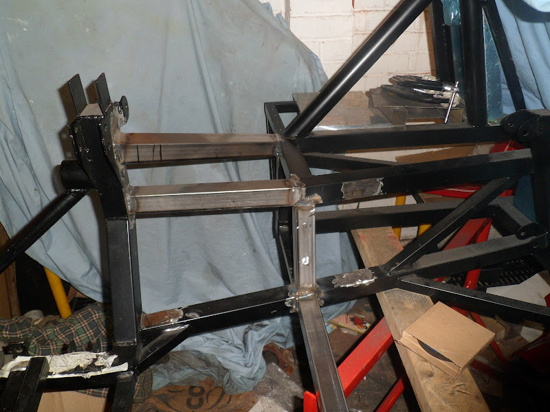
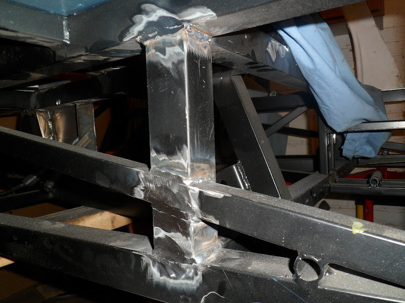
Unless that is I remove the sump (both parts which I think would involve removing the gearbox) every time I want to take it in or out. I don't really fancy that.
Not to fear, I have a plan, bolt in plates it is. Back to the angle grinder and welder!
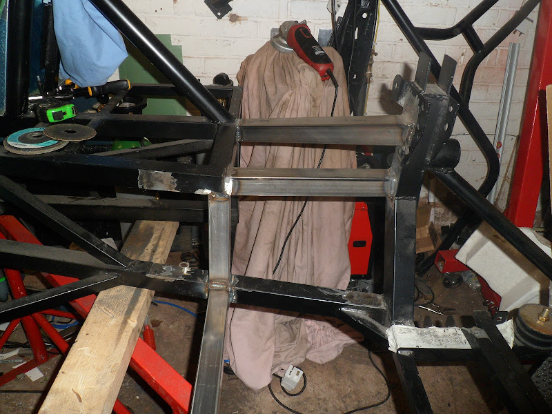
Basically it er doesn't fit in with them in place! =8-o
Unless that is I remove the sump (both parts which I think would involve removing the gearbox) every time I want to take it in or out. I don't really fancy that.
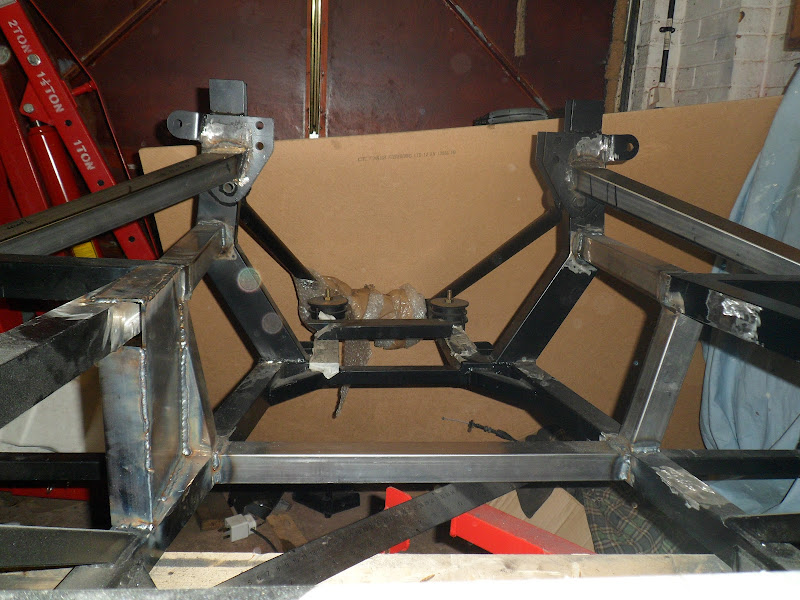
Not to fear, I have a plan, bolt in plates it is. Back to the angle grinder and welder!


")


")