Gt40-v10

I thought it time to start a build thread for our new project. This has been in the pipeline for over a year now, but have finally cleared some space on the schedule to get it underway. It must first be made very clear that this car is not being built to compete in any specific category of racing, save for the possibility of running it in an outright class of hill climbs occasionally – just for fun. It’s real purpose will become clear later, but for now, just enjoy.


Ok, so here is the premise…


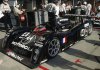
GT40-V10. That’s right, V10! The 950hp+ Cosworth TJ2005 3ltr V10 to be more precise. These specific engines were run by a number of F1 teams in 2005, by Toro Rosso in 2006 (limited to 18,000rpm), and are still employed in the Red Bull demonstration team in their chassis. They turn in excess of 19,000rpm in full trim, though for obvious reasons, we’ll be running it on reduced revs to extend the rebuild intervals. We’re shying away from PI Research engine management and logging at this point, and looking at a locally developed MoTeC solution.


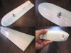
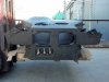
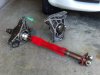
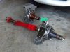
So it’s this, solid mounted to an LMP carbon chassis, with Renault Formula 1 suspension, 6 speed sequential transmission with integral suspension mounts, full carbon GT40 body and good old pin-drive 15” BRM wheels custom machined to suit the Renault uprights / hubs.


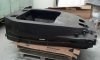
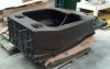
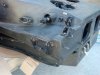
The chassis was flown in from the US a couple of weeks ago, and we’re currently producing CAD files of it to enable accurate production of all the necessary components. The suspension components are amazing. The body will remain relatively standard with subtle aero tweaks and tricks (under and through the skin!) to substantially increase front end downforce. The ground effect diffuser and floor currently being CFD’d will stick the rest of the car to the track.


We have guys inside F1 working on this with us, as well as some very talented people out here in Australia. I have a lot of info and pics that I’ll be sharing about the car in the very near future, but there you go! It’s out there… Flame away :)
 

Ian Anderson

Lifetime Supporter
Will it have / is it even possible to make a V10 cross over bundle of snakes?

This is going to be an incredible mating of current technology and 60's body styling

Ian
 
Sounds an interesting project.

As for some very talented people in Australia... they must be Brits working out there !
 
Hi Ian, the current design has the headers (very short, made from Inconel) exiting through the floor at the beginning of the tunnels, effectively 'blowing' the air through the tunnels - increasing downforce. Though this sounds logical, the exhaust gasses create an extremely turbulent airflow through there.

Can you imagine though? ;)
 
Wow......:stunned:
One things for sure, your not leaving much room for future upgrades, you've already got them.

Was surprised to see your RF sold, now I know why.
Will be watching your 'outside the box' build with great interest.

As for some very talented people in Australia... they must be Brits working out there !
What, the ones that were sent out on the convict ships ;)

Clayton
 
Wow!

Impatient to see some pics of the parts!

What kind of gearbox is able to move a let's say 1ton (maybe a bit more?) with such wheels, with a 18k rpm as an imput? A challenge in itself unless I'm totally wrong...

A least, a formula one with a roof and doors! Great!

Olivier.
 
Weight is not a concern, the car will be well under current LMP weight limits. These engines produce a lot of power, however the torque figures are (comparatively) tame. The transmission, while not a bespoke item, is certainly not a common one. Hewland have been great with providing the design for our specific requirements. The three most critical factors in selecting the correct 'box for this project are...

1. Length from engine mounting face to output shaft (including bell housing)
2. Height of input shaft (F1 V10 crank center line is only 58mm from base!)
3. Available ratios to suit 18,000rpm input shaft speed.

We have the option on a couple of team F1 transmissions, but the electronics / hydraulics required to operate these gearboxes is complex, to say the least. Also, genuine F1 transmissions run very narrow gears, so we've opted for something that'll give us better part life cycles.
 
Looking forward to pics Troy, this will be one awesome project.....Can I have first drive Mate??? :thumbsup:
 
Troy, this is awesome. I can't wait to see pics and videos. I'm in Brisbane, so maybe some day I'll be lucky enough to see it in the flesh.
 
Troy, the surfs been woeful so you need something to keep you busy.

Slight tangent but....U seen the latest swell forecast. Your ole WA is gonna be massive but onshore... Biggest winter storm this season crossing the Indian Ocean as we speak. I'm on a plane 1st thing Sunday morning chasing it! Not telling where.....Yeow!
 
Hi Simon, excellent - will have to host a BBQ at the workshop soon!

Matt, you're a lucky man. Though keep an eye out for those big fish with the teethy grins - WA has seen more than their fair share this year. Heading North or South?

I've been surfing my 5'3 Tuna for the past 2 weeks (pic attached). It's an epoxy Alaia with huge concave. Extra fun in the early morning glassy conditions. No fins is a big challenge, but I've already packed my wetty away, and am sitting tight, waiting for the QLD cyclone season to begin.
 

Attachments

  • seaglass_project_tuna.jpg
    seaglass_project_tuna.jpg
    71.8 KB · Views: 619
Hi Ian, the current design has the headers (very short, made from Inconel) exiting through the floor at the beginning of the tunnels, effectively 'blowing' the air through the tunnels - increasing downforce. Though this sounds logical, the exhaust gasses create an extremely turbulent airflow through there.

Can you imagine though? ;)

I heard a number of F1 teams used to do this (IIRC it's now banned). Only issue with it is that it makes things unpredictable, the amount of downforce is dependant on revs, if you lift or change up you lose downforce!

Great project through, can't wait for some pics! :)
 
CAD modelling of the chassis is now almost complete. Out of interest, I weighed the tub yesterday. She came in at 96.1kgs with steering rack, fuel cell, suspension mounting points, gear lever, master cylinders and aluminium bulkhead plate fitted.

If you've not been following the RCR LMP thread, here is what my chassis looks like. And the last pic is of the actual car that this chassis is from. The tub sustained heat damage to sections of the skin and core on the left hand side which are currently being repaired. The damage was caused by an incident at LeMans in 2001.
 

Attachments

  • Tub side.jpg
    Tub side.jpg
    107.5 KB · Views: 684
  • Tub rear.jpg
    Tub rear.jpg
    119 KB · Views: 762
  • Tub fr side.jpg
    Tub fr side.jpg
    172.3 KB · Views: 626
  • Tub front.jpg
    Tub front.jpg
    163.8 KB · Views: 645
  • lm0004.jpg
    lm0004.jpg
    67.9 KB · Views: 707
Here are a couple of the less detailed CAD models of the tub integrating with the engine / trans mock up. The front suspension geometry is vastly different to how this car was originally designed, and is posing some extra challenges with steering track rod placement - given the adaption of the Renault F1 uprights.

Packaging the components within a 1968 GT40 body's constraints is the other issue we have. The LMP cars had a wheelbase of 2920mm, where a GT40 is only 2438mm - That's 482mm I have to lose! Even though the V10 is only 591mm front to back, the transmission's to suit these engines have their gear clusters inboard of the differential, making for a longer transmission case. Oh, did I mention that the input shaft height is only 58mm? (same as the crank centerline height from the base of the engine)!

The uprights themselves (Titanium) are very cool pieces. I have added a couple of pictures of 1x front and 1x rear. Much care (and extra $) were spent ensuring matched pairs front and rear. F1 cars being prototypes, are constantly evolving throughout each season, and finding matched stuff like this can take time. The drive shafts and tripod joints on the rears are extremely light.
 

Attachments

  • GT40V10 a.JPG
    GT40V10 a.JPG
    75.4 KB · Views: 578
  • GT40V10 b.JPG
    GT40V10 b.JPG
    71 KB · Views: 586
  • Uprights 1.jpg
    Uprights 1.jpg
    140.8 KB · Views: 680
  • Uprights 2.jpg
    Uprights 2.jpg
    175.5 KB · Views: 599
Back
Top