
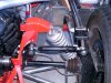
Let me start some discussion on the GTD40 rear suspension geometry and camber (with the original chassis).
On assembly of the rear suspension, I noticed the top arm was quite inclinated.
This means on compression, the camber will become progressively stronger.
Something which is needed but too much to my opinion.
Better, to my feeling is to put the top bracket 60 mm (2.4" higher).

Therefore I started to investigate, calculate and measure.
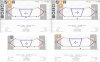
The graph below is some DIY measurement using a small laser projecting on a graph.
Vertical axis is the displacement of the wheel in millimeters.
Horizontal axis is converted to camber degrees.
The Dark blue line is the initial camber measured when compressing the rear suspension. Almost 3.5 degree of camber change.
The blue dotted line is the calculated line on the change (60 mm higher position of bracket) and aiming for a 1 degree camber change.
The red line is the measured new camber envelope.
The measurements had some hysteresis due to some play between brackets and bolts (which will be resolved later on).

I am quite happy with the result.
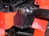
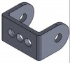
Now the challenge is to put the bracket 60 mm higher while staying away from the reinforcement plates and it bolts. Decided to remove reinforcement plates and design a new bracket which
1) replaces both brackets
2) saving weight
3) being more stiff
4) a new position for the torsion bar
5) a new position for the top arm brackets
6) and still able to use the old location as well.

I know the idea is not new, Mike told me Roy Smart did it already in the past. Probably for a good reason :thumbsup:
If you want to have the drawing to make this bracket, let me know.
And please share your experience since this is all theory...still.
On assembly of the rear suspension, I noticed the top arm was quite inclinated.
This means on compression, the camber will become progressively stronger.
Something which is needed but too much to my opinion.
Better, to my feeling is to put the top bracket 60 mm (2.4" higher).
Therefore I started to investigate, calculate and measure.
The graph below is some DIY measurement using a small laser projecting on a graph.
Vertical axis is the displacement of the wheel in millimeters.
Horizontal axis is converted to camber degrees.
The Dark blue line is the initial camber measured when compressing the rear suspension. Almost 3.5 degree of camber change.
The blue dotted line is the calculated line on the change (60 mm higher position of bracket) and aiming for a 1 degree camber change.
The red line is the measured new camber envelope.
The measurements had some hysteresis due to some play between brackets and bolts (which will be resolved later on).
I am quite happy with the result.
Now the challenge is to put the bracket 60 mm higher while staying away from the reinforcement plates and it bolts. Decided to remove reinforcement plates and design a new bracket which
1) replaces both brackets
2) saving weight
3) being more stiff
4) a new position for the torsion bar
5) a new position for the top arm brackets
6) and still able to use the old location as well.
I know the idea is not new, Mike told me Roy Smart did it already in the past. Probably for a good reason :thumbsup:
If you want to have the drawing to make this bracket, let me know.
And please share your experience since this is all theory...still.
Last edited:
") Most compared it to the earlier 911 P cars in terms of breaking away at the rear. Certainly you had to treat the car with respect and pick your moments with care! However in their hey day GTDs were pretty much the only replica on track in the UK and of the others, they couldn't match the GTD pace. That's all moved on now with new replicas coming to the market which is all good news for everyone.
Most compared it to the earlier 911 P cars in terms of breaking away at the rear. Certainly you had to treat the car with respect and pick your moments with care! However in their hey day GTDs were pretty much the only replica on track in the UK and of the others, they couldn't match the GTD pace. That's all moved on now with new replicas coming to the market which is all good news for everyone.