Has anyone bought or seen the quality of any of the plans from Project Diablo?
Project Diablo - Your inteernet sorce for supercars blueprints
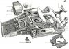
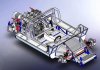
They want $159.99 for:
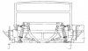
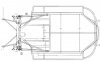
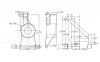
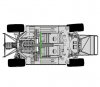
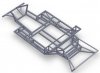
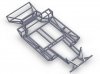
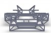
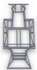
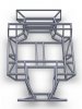
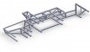
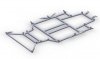
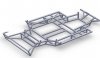
Btw, those jpgs come from an autocad drawing which is (or was) floating round the net.
Druid
Project Diablo - Your inteernet sorce for supercars blueprints
They want $159.99 for:
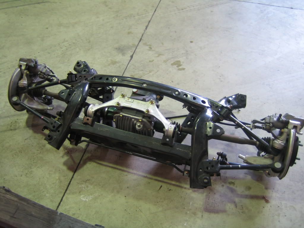
More than 80 pages usefull information. More than 70 body patterns. Short description of the process of molding. High quality photoes. Full technical specification. A CD with the complete 3D model of the car in 3D Max and Autocad format. Also including dashboard, seats, etc. Frame design included only with this car.
Btw, those jpgs come from an autocad drawing which is (or was) floating round the net.
Druid
 ffice
ffice ></o
></o") ) and then sell what I don't need. If I'm really lucky selling the bits and pieces will pay for the rest of the car but I'm not holding my breath for that.
) and then sell what I don't need. If I'm really lucky selling the bits and pieces will pay for the rest of the car but I'm not holding my breath for that.