
You are using an out of date browser. It may not display this or other websites correctly.
You should upgrade or use an alternative browser.
You should upgrade or use an alternative browser.
Help - GT40 Space Frame Drawings and Plans
- Thread starter Kevern
- Start date
Integrator
CURRENTLY BANNED
My name is Metin friend.
Thnaks
Thnaks
Integrator
CURRENTLY BANNED
I did some more. But this chasis seems weak. My estimate weight nearly 120 kg.
hi out of interest what program did you use to make that mock up and would you be willing to share it?
Many thanks in advance.
Jordan.
ps. curtis thanks for your emails
Welding (or structurally riveting) sheet steel to the tubes will help a lot. You're missing much of the diagonal stuff to prevent lozenging.
The rear bay in back of the rockers needs more horizontal structure. Put a horizontal load on it and all the tubes are in simple bending mode.
The rear bay in back of the rockers needs more horizontal structure. Put a horizontal load on it and all the tubes are in simple bending mode.
Looks a lot like a Tornado space frame.
Hi Metin.
Two good books to read to help you understand Chasiss geometry etc.are
HOW TO MAKE YOUR CAR HANDLE, by Fred Puhn....HP Books
Competition Car Suspension Design Construction Tuning, by ALLEN STANIFORTH....Haynes books
There are many things to concider when deciding on your suspension mounts, but a good starting point would be to have
your bottom wishbone mounts parralell to the ground
your top wishbones, 2 thirds the lenght of the bottom ones, and angled down towards the chasiss at an angle of 15 degrees...your rear top wishbones would want to be at a slightly steeper angle
your rear radius rods, would want to be parralell, to the ground when your suspension is halfway compressed
This is just a rough guide, no doubt someone will say its wrong......but you really need to read these books, and make your own decisions
I hope this helps
mick
Simon, I've been signing off with Druid online for ~15 years but fwiw I'm David.
Anyway after more considering and reading up of race car construction I've begin to consider a second approach instead of a spaceframe. Glued aluminium honeycomb similar to the J-car/Mk IV, (although for me its got to be a Mk I body).
Not that I'm particularly interested in authenticity. I'd *love* an original (or one of the 'to original plans' replica's) but as I can't afford either I'm going to have my interpretation of it. It'll look like a Mk I and it'll have a V8 but beyond that I'm going to make it as modern as possible.
Has anyone ever duplicated the Mk IV honeycomb chassis? Or got any pictures of the chassis itself? I've got a few but they seem to be at odds with the description of it being a glued chassis as it appears riveted. Of course it could still be glued and the glued joints reinforced by riveted plates...

Druid
Anyway after more considering and reading up of race car construction I've begin to consider a second approach instead of a spaceframe. Glued aluminium honeycomb similar to the J-car/Mk IV, (although for me its got to be a Mk I body).
Not that I'm particularly interested in authenticity. I'd *love* an original (or one of the 'to original plans' replica's) but as I can't afford either I'm going to have my interpretation of it. It'll look like a Mk I and it'll have a V8 but beyond that I'm going to make it as modern as possible.
Has anyone ever duplicated the Mk IV honeycomb chassis? Or got any pictures of the chassis itself? I've got a few but they seem to be at odds with the description of it being a glued chassis as it appears riveted. Of course it could still be glued and the glued joints reinforced by riveted plates...
Druid
Last edited:
The chassis components were all riveted, but most of the critical pieces were also glued.
Hi David,
There is a thread in this section,on page 4 called..
....chassis design, useing honycomb core....... there is some usefull info there
here are a few links to help with riveting
Aircraft Construction, Riveted Joints
http://rgl.faa.gov/REGULATORY_AND_G...9baac81b86256b4500596c4e/$FILE/Chapter 04.pdf
Avdel Global :: Avex®
This adhesive is used in the manufacture of both commercial, and aerospace honycomb
http://www.ambercomposites.com/downloads/datasheet/araldite-420-tds-v1.pdf
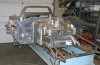
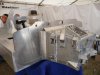
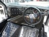
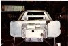
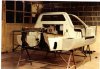
There is a guy in USA making 10, I think. mk IV..J cars, his name is Kenny Thompson here are some pics of his, and other cars
I hope this helps
mick
There is a thread in this section,on page 4 called..
....chassis design, useing honycomb core....... there is some usefull info there
here are a few links to help with riveting
Aircraft Construction, Riveted Joints
http://rgl.faa.gov/REGULATORY_AND_G...9baac81b86256b4500596c4e/$FILE/Chapter 04.pdf
Avdel Global :: Avex®
This adhesive is used in the manufacture of both commercial, and aerospace honycomb
http://www.ambercomposites.com/downloads/datasheet/araldite-420-tds-v1.pdf
There is a guy in USA making 10, I think. mk IV..J cars, his name is Kenny Thompson here are some pics of his, and other cars
I hope this helps
mick
Attachments
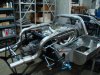
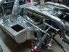
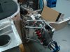
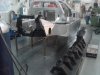
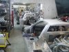
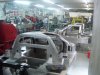
A few more pics.
I have about 30 pics, most of them I found on this site
mick
I have about 30 pics, most of them I found on this site
mick
Attachments
Hi Mick,
Thanks for the links and pics, I'd not previously considered the J-cars/Mk IV as I prefer the look of the Mk I so while I knew it was aluminium I didn't really 'twig' as to it being honeycomb so I have few pics of it.
I read the thread on honeycomb core after I'd posted my response. It was actually that same book mentioned "How to Build Motorcycle-engined Racing Cars." that piqued my interest in honeycomb in the first place.
The main advantage I see is that it can be prototyped, first in styrene at 1/10 (very easy to divide every measurement by 10) and then full scale in MDF *very* cheaply[1] and relatively easily, a router is really all you need. Reinforcement, bobbins, mounting points can all be designed and trialled long before the expensive part. As I see it *everything* should sorted[2] before you have to commit to making it and by that point you shouldn't need to redesign or modify. Even up to that commit point of buying the sheets a space frame is *still* an option as with a bit of planning everything can just be fitted to that instead.
Down side is that it has to be very *very* carefully planned and built otherwise it will just fall apart. Reading more on the subject I've realised that the J-cars/Mk IV's are bonded with the edging strips and reinforcements riveted to prevent peel.
I'm pretty much decided that I'm going to do it, rather than wait years until I have the cash for the larger bits or a kit I can start small *now*, knowing that I can adjust easily before I have to commit. As it stands I already have the front hubs/arms/brakes/rack, I know what wheels and have a set I can borrow, I think I know what I want for the rear suspension (I'm just waiting for the uprights to come up for a decent price on ebay), how I want to do the suspension[3], I have a pretty good idea on the engine (4l 32v V8) and transaxle (6sp Audi), I know track and wheelbase[4] so now it boils down to do I buy bodywork or make it.
Back onto the original subject however plans would still be very handy, I'm very roughly basing my plan on the (poor) autocad plans that have been floating around since 2004 (based I believe on an ERA GT40) with various other measurements gained from various sources over time.
Druid
[1] I estimate 6 sheets at ~£10ea, in comparison honeycomb sheet is £200+ea, Technical Resin Bonders says £203+ which is for 13.70mm/0.5mm facing, "How to Build Motorcycle-engined Racing Cars." suggests 15m with 1mm facing which given that the J-cars/MK IV used 1/2inch seems a good suggestion.
[2] Up to the point of having a drivable car that you can't drive because it'd fall apart if you did!
[3] I figured seeing as its GT40 'inspired' rather than a replica I may as well upgrade to modern suspension so inboard shocks.
[4] Going to make it 'stock', shorter than the (wider tracked) frontend donor so given that this makes it less Ackerman and the donor is already a pretty good handler this should make it rather direct on the steering and faster reacting!
Well for those still after plans I've come across these, not had a full look yet but seems at the very least to be the autocad originals for the jpeg's that are floating around, sectional body plans and some plt files.
No promises of any accuracy (in fact I believe others have already commented that these are far from accurate).
Have fun.
http://kit-car.org/Files/other_kit-car/gt40.rar
Druid
No promises of any accuracy (in fact I believe others have already commented that these are far from accurate).
Have fun.
http://kit-car.org/Files/other_kit-car/gt40.rar
Druid
I had a look at those plans last night and they really are poor. At first glance they look ok but zoom in and it all goes to hell. The 'sections' are flattened (slightly) variable width 'slices' (about 1/4inch) rather than zero width, spaced (slightly) irregularly and too far apart IMO (about 8.5inch). It looks to me to be copied (badly) from a 3d model. Still, something could be based on them but would take a lot of work.
Druid
Druid
Hi David,
You either need to get a body, or get some critical measurements, off a GT 40 chassis. to be able to make a correctly dimensioned chassis
I dont know where you live , but if you are near me, ( im in hampshire )you are welcome to come and take some dimensions of my chassis.
mick
You either need to get a body, or get some critical measurements, off a GT 40 chassis. to be able to make a correctly dimensioned chassis
I dont know where you live , but if you are near me, ( im in hampshire )you are welcome to come and take some dimensions of my chassis.
mick
Hi guys, have only recently come across this GT40 thread, hence this is my first post, I too got the AutoCAD file discussed earlier, it was several years ago and indeed it is the Tornado plans. Back around 2005 or 2006 I drew it up using an older version of Solidworks, since then I have not updated it, but have saved an E-drawing version that can be viewed in 3D for free by anybody even if they do not have the Solidworks program. If necessary you might have to download the free Edrawings viewer if it doesnt work, found easily on the net. In order to see it rename the file extension that it reads GT40.easm instead of:
GT40 OVERALL rename file extension to easm .pdf
If anybody has difficulty opening, renaming or viewing let me know and i can email it directly to you, and if anyone would like the original Solidworks files also i can oblige.
Kind regards,
Joey
GT40 OVERALL rename file extension to easm .pdf
If anybody has difficulty opening, renaming or viewing let me know and i can email it directly to you, and if anyone would like the original Solidworks files also i can oblige.
Kind regards,
Joey
Attachments
Hi again folks, at risk of reposting sizes that may have been put up before, here are basic dimensions of the real GT40...
Basic Dimensions
Wheelbase: 95 in. (2413mm)
Track, front and rear: 55in. (1397mm)
Length: 168 in. (4265mm)
Width: 70 in. (1778mm)
Height: 40.5 in. (1028.7mm)
Miscellaneous Heights
•Base of windscreen: 28.25 in. (717mm)
•Top of windscreen: 39.2 in. (970.3mm)
•Top of steering wheel: 31.35 in. (796.3mm)
•Minimum ground clearance: 4 in. (101.6mm)
Joey
Joey
I am having difficulty opening the file.
Please email it to me at [email protected]
Thanks
Andy
I am having difficulty opening the file.
Please email it to me at [email protected]
Thanks
Andy
Worth mentioning that's for the MK1
I have the following figures where they differ.
Mk2: Length 163 in., Front Track 57 in., Rear Track 56 in.[1]
Mk3: Length 169 in., wheelbase of 95.5 in.
Mk4: Length 173 in., width 70.5 in.)
Druid
[1] Although the comment in the text accompanying the specs is "Wheelbase remains the same as the MK I at 95 in., tread is increase 1 in. to 57 at the front and remains 56 in. at the rear."
Then again I also have noted that the prototypes were 54 in. Front/Rear.")
I have the following figures where they differ.
Mk2: Length 163 in., Front Track 57 in., Rear Track 56 in.[1]
Mk3: Length 169 in., wheelbase of 95.5 in.
Mk4: Length 173 in., width 70.5 in.)
Druid
[1] Although the comment in the text accompanying the specs is "Wheelbase remains the same as the MK I at 95 in., tread is increase 1 in. to 57 at the front and remains 56 in. at the rear."
Then again I also have noted that the prototypes were 54 in. Front/Rear.
Integrator
CURRENTLY BANNED
Dear Jordan
Sorry for my late reply. I used SolidWorks for this 3D chassis model. Dimensions are based on the plans that were posted by Chris Melia.
http://www.gt40s.com/forum/221206-post17.html
http://www.gt40s.com/forum/221208-post18.html
Resulotion of these pictures are very bad and impossible to read some dimensions, but I think my drawing is 98% correct according to these plans.
Of course I'll share my drawing. File is in my other computer. I'll share in these days.
Similar threads
- Replies
- 1
- Views
- 764
- Replies
- 11
- Views
- 1K