Initial alignment observation help.

Ken Roberts

Supporter
I'm doing some initial alignment adjustments to the front suspension and came across this observation.

The drivers side upright sticks out farther than the passenger side by approx. 3/8". If you were to draw an imaginary centerline for the chassis and then measure out to the tub wall where the upper and lower control arms bolt to you'd find that the passenger side measurement is 3/8" less than the driver side measurement. I'm sure this would be caught when you attempt to do the string line measurements.

Has anyone else observed this? This means that the drivers side upper and lower control arms must be initially adjusted in farther than the passenger side. Driver side should be moved in 3/16" and the passenger side moved out 3/16". This is assuming that you started with both sides the same.

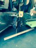
The picture is showing you that this particular measurement is not the same from one side to the other (3/8" difference). I have a 4' straight edge running along the side of the passenger tub.

 
Last edited:

Ken Roberts

Supporter
When I adjusted my initial camber and toe in settings I noticed I only have about 3/4" thread engagement on the tie rod ends. The rack shaft has engraved right on it that "minimum thread engagement of 1" is required.

 
Last edited:
Ken
The control arms, uprights and suspension pockets are all ambidextrous, they are the same components engineered to be used on both sides of the car.
This obviously means that if the heim joints are equally set on both sides of the car they will be same.
The centerline you have chosen to use cannot be the true center of the car
 
Last edited:

Ken Roberts

Supporter
Fran a 4 foot straight edge was aligned with the outer wall of the tub then measured in to the control arm mounting wall area of the tub as in this picture. There was a difference in measurement from one side to the other of 3/8".

You can even see it with the naked eye if you sight down one side and then compare it to the other. The wheel hub/rotor sticks out farther on the drivers side. (with the body off)


I have confirmed that the suspension components are equal on each side. It's the chassis that is out. Repeat the measurements as I have done with a straight edge running down both outer walls of the tub.

To reconfirm my observation I have adjusted "IN" the rod ends of the upper and lower control arms as far as they can go on the drivers side and adjusted "OUT" the passenger side 1/8". Now when I sight down the side of the chassis the front rotor/hubs stick out the same on both sides.

Control arm rod ends were adjusted equal initially on both sides. Drivers side rotor/hub stuck out 3/8" farther than passenger side. Adjusted driver side rod ends in 1/4" and adjusted passenger side rod ends out 1/8". Now they look equal when sighting down both sides. Measurements of depth of wheel well (see picture) confirms that passenger side is 3/8" deeper than drivers side.
 

Howard Jones

Supporter
Here's what I know about my car. When I took delivery a couple of years ago I took all the bodywork off and measured the chassis cross wise front to back and then side to side. I used the forward most lower a A Arm pick up points and the opposite rear most lower A Arm pickup points. If you really what to get accurate, use the centerline of the holes in the chassis as a point of reference and not the "U brackets". In the front measure into the housings to find the center of the holes in the pickup point housings (pockets).

LF to RR and RF to LR. Then made measurements from RR to LR and RF to LF. They all came out to less that 1/16" dead on square. That was the limit of my resolution really. Then I put a scratch on the bottom of the tub in front that represented the center of the front and then did the same on the chassis transverse tubing under the rear of the gearbox.

That's my center line. From there I did a basic square it up A Arm setup when I put the car together.

This wasn't the most fun thing I've ever done but it did tell me the car was square from the get go. Pretty important point.

The reason I did this right from the start was that my GT40 (GTD) was so difficult to make the body fit. It did turn out that the body was the problem but checking out the chassis for squareness after the fact was a pain in the ass on that car so I did it first thing on my SLC.

Use my method (suspension pickup points as datum's) to check that the chassis is true and set a center line that way. You will be certain about what you have then.
 

Ron Earp

Admin
LF to RR and RF to LR. Then made measurements from RR to LR and RF to LF. They all came out to less that 1/16" dead on square. That was the limit of my resolution really. Then I put a scratch on the bottom of the tub in front that represented the center of the front and then did the same on the chassis transverse tubing under the rear of the gearbox.

That's my center line. From there I did a basic square it up A Arm setup when I put the car together

We did something similar on the Lola. Suspended the car level and used a bob to drop off the center of pickups with a bolt, as well as corners of the tub, onto the ground. We were very square to the resolution that we felt we could reliably measure,about 1/16". It was a beast of a job to make those measurements as you've got to be level and square to the floor which was an undertaking on itself.
 
If i recall right (and this is going back several years now) I had a similar observation about the difference in the driver and passenger side.

But it doesn't really matter - set ride height, center the steering rack, set toe roughly, then set caster/camber, bumpsteer, then toe and done.

Minimum safe engagement for steel thread is size*1.5, so 1/2'' would be 3/4'' engagement. Again, if i recall right I think one of my steering arms ended up being 7/8'' and it hasn't failed after 4 or 5yrs.
 

Howard Jones

Supporter
It can be done alone............but you really need two people and pretty much a full day. The other way is a good alignment shop and a checkbook. Tell them what you want and come back later. That will work just as well I guess.
 
I made four of these alinement plates one for each rotor to take all the guess work out of it, with the car planted on the ground and some extra weight added. I got it pretty close.
I found that the distance from the front rotor to rear were out with all the adjustment in on one side and out on the other. I couldn't get it the same so close had to be good enough.
as long as there pointed in the right direction It should be good even 1/2" out shouldnt really make much difference.
 

Attachments

  • wheel alinement.jpg
    wheel alinement.jpg
    99.6 KB · Views: 190
Back
Top