As per usual, very nice write up Joel.
Regards Brian
Regards Brian

As per usual, very nice write up Joel.
Regards Brian
Joel,
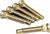
It may be too late now but I'd suggest using wheel studs with rounded unthreaded ends. ARP makes them. This makes starting the nut easier and prevents cross- threading. SCTA requires 1" across hex nuts so that they provide a wider contact area on the wheel. This reduces the chance that the nut could pull through the wheel.
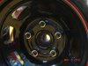
Be sure you check with your wheel manufacture. I found that there are several different manufactures lug nuts that won't fit correctly with the GM ZO6 wheels I use. In the end I bought some GM replacement USA lugs for the ZO6 wheels I use. All good. Beware cheap Chinese lug nut knockoffs.
By the way I have that same press that I bought for the same purpose. I have used it quite a bit since. Kind of small working area but after all its pretty cheap.
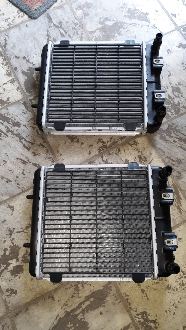
Thanks Ken, I have been waiting for GM to start selling these Which they recently added to their parts web site. I asked the gentleman who is selling them the size of the core just to compare.Here is a set of C7 ZR1 intercooler rads that might be a good option in the future. They are adequate for the 750hp LT5 engine.
ZR1 Heat exchanger L/R (intercoolers) - CorvetteForum - Chevrolet Corvette Forum Discussion
C7 Parts for Sale/Wanted - ZR1 Heat exchanger L/R (intercoolers) - ZR1 Heat exchanger L/R (intercoolers) new never used $175.00 each https://cimg6.ibsrv.net/gimg/www.corvetteforum.com-vbulletin/2000x1124/20200318_113421_37d9a19976271873df58fa41c831bb9325ac4f59.jpg eachwww.corvetteforum.com
View attachment 105100
Joel,
While size is a good metric to compare to stock capacity, not all cores are equal and air flow is critical. It's my understanding that the stock rear vents don't get great airflow so you might consider enlarging them and adding some ducts as others have done. No matter what I'd plumb them in parallel. If the core size/quality and airflow are the same as the single stock unit and you plumb your two units in parallel. you'll reject more heat.
Joel,
The stock unit appears to have long rows. If all things are equal, you get better heat rejection from a form factor with more short rows than one with a fewer number of long rows. Even though the surface areas are the same, the fluid cools as it flows through the row. This reduces the delta T which has an exponential effect on thermal transfer. If you were to look at a heat rejection map you would see a gradient across the row. Short rows and parallel heat exchangers both maximize delta T which increases heat rejection. Most heat exchanger choices are driven by fitment, but this is what I did: best core for the budget, biggest core that would fit, shortest rows, lots of air, good pump.