Ken's SLC build thread

Ken Roberts

Supporter
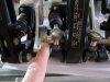
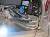
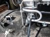
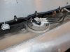
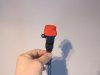
To help prevent the remote wheel from being adjusted without your knowing (say for example some youngster sits in your car at a car show and starts spinning the wheel for fun) I plan to install the jam nut on the left side of the threaded rod as in this picture for extra insurance once I have it set up correctly. You could remove the jam nut if you plan to track the car then reinstall for street driving.

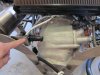
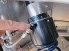
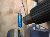
My finger is pointing to the jam nut.
 

Attachments

  • 014_zpsbax9o0er.jpg
    014_zpsbax9o0er.jpg
    94.6 KB · Views: 248
Last edited:

Ken Roberts

Supporter
The brass fittings in the brake residual valves can be removed without damage with some heat from a heat gun as shown in the picture. Do not try to remove them without first applying heat.
 

Attachments

  • 016_zpsqofcebqi.jpg
    016_zpsqofcebqi.jpg
    81 KB · Views: 216
Last edited:

Ken Roberts

Supporter
Back to working on the car once more. Clipping is the theme currently. Making sure everything is supported where it needs it. I make the majority of clips out of 1/4" aluminum angle. The cushion clamps are help to it with either 10/32" scews or 1/4" bolts depending upon the weight of the item. Mock up bolts are used up until I get finished then a quick tally will tell me how many to order in what sizes.
 

Attachments

  • 003_zpszuno1nsm.jpg
    003_zpszuno1nsm.jpg
    104.9 KB · Views: 254
  • 005_zpscwbuwoz5.jpg
    005_zpscwbuwoz5.jpg
    112.6 KB · Views: 235
Last edited:

Ken Roberts

Supporter
Mocking up the coolant and A/C hose path. A trim panel will be fitted in the passenger foot well area with a thermal barrier to hide the coolant, A/C lines and body control module.
 

Attachments

  • 009_zpsmygxaa48.jpg
    009_zpsmygxaa48.jpg
    106.9 KB · Views: 227
Last edited:

Ken Roberts

Supporter
Built the prototype A/C piping for the condenser. The goal was to have both #6 and #8 hoses on the passenger side. In this picture (to the left) you can see the mock-up of the wiring disconnect for the front hood.
 

Attachments

  • 007_zpsv13mjga4.jpg
    007_zpsv13mjga4.jpg
    140.7 KB · Views: 244
Last edited:

Ken Roberts

Supporter
Finished the mock-up of the 1/4" coolant air bleed line back to the tank. It's held to a aluminum tube with heat shrink wrap for support.
 

Attachments

  • 002_zpsdfwbexjn.jpg
    002_zpsdfwbexjn.jpg
    95.8 KB · Views: 263
Last edited:

Ken Roberts

Supporter
Converted the LS9 supercharger blower pulley to a hub with a unbolt able pulley. Installed is a 2.6" pulley. By simply installing this smaller pulley and then a retune you go from the stock 638hp to 680hp.
 

Attachments

  • 001_zpsz6cjmgka.jpg
    001_zpsz6cjmgka.jpg
    108.4 KB · Views: 283
Last edited:

Ken Roberts

Supporter
To the left in the picture you can see a fuel level sensor temporarily tie wrapped to the harness. The C6 Corvette has two fuel tanks with two level sensors. Since I'm only using one tank with one sensor I have to trick the ECM in to thinking that the passenger side tank is empty. The C6 Corvette fuel system always uses up the fuel in the passenger side tank first. The gauge interprets this as half full to full. Then the ECM watches the fuel being used in the driver side tank and interprets it's level as being from half full to empty.

My C6 Corvette fuel level gauge will display half a tank as "full" to me. The level sensor (for the pretend passenger tank), as shown in the picture, is set to 41ohms which is interpreted as empty to the ECM.

The left tank must always drain before the right tank. Otherwise the ECM is confused and a code will set and the gauge will be defaulted to zero. So the only way for me to use the C6 gauge is to trick the ECM with the fake passenger fuel level sensor. Once I determine that it works correctly the sensor can be replaced with a 40 ohm resistor.
 

Attachments

  • 013_zps9w0msgox.jpg
    013_zps9w0msgox.jpg
    91.6 KB · Views: 248
Last edited:

Ken Roberts

Supporter
I finally decided on how to disconnect the rear hood wiring harness easily. My finger is pointing to the harness connector location in front of the license plate area. I will flip up or down the license plate to access the quick disconnect. My front and rear hoods are installed like the race car hoods without a hinge system so I need a quick way of disconnecting electrical power.
 

Attachments

  • 014_zpsjn9vae8y.jpg
    014_zpsjn9vae8y.jpg
    109.3 KB · Views: 237
Last edited:

Ken Roberts

Supporter
I'll be upgrading these aluminum 90 degree fitting to steel shortly. I just don't feel comfortable with the provided fitting. This fitting will be under slight stress since the ram is not held stationary. The only thing stopping the ram from turning over time is the braided hose and fitting. Harmonics and vibration transmitted through the suspension over time might have an effect on them.
 

Attachments

  • 004_zpsqajpln5v.jpg
    004_zpsqajpln5v.jpg
    105.2 KB · Views: 247
Last edited:

Ken Roberts

Supporter
A fuel pump inertia switch was added for safety. Consideration for a "easy access" location was needed in case it needs to be reset. It's simply wired to the low current ground side of the fuel pump relay. This type is readily available and is sold by AC Delco. Part number is #D1876D. Cost is about $70.

UPDATE- the switch was later relocated to the side of the hand brake housing. The front position interferes with the finished side panel
 

Attachments

  • 016_zpsymatr9yv.jpg
    016_zpsymatr9yv.jpg
    78.7 KB · Views: 225
  • 002_zpsqeh8kl1c.jpg
    002_zpsqeh8kl1c.jpg
    51.1 KB · Views: 265
Last edited:
Ken, your divergence off the well trodden build path is cool. I always look forward to seeing what you've done next. And, I don't know how I missed (forgot) that you are doing a LS9....your car when done is going to be pretty special. -- Mike
 

Ken Roberts

Supporter
Thanks Mike. Taking all these side roads has led to an extended build time but that's okay. I retire next June so I'll have a lot more time on my hands to play. The LS9 engine will be for my next RCR car. Either a GTR or a GT40 MK4.

How's the driving experience so far with your SLC Mike?
 
Last edited:

Ken Roberts

Supporter
Anybody have an SLC dash for sale? I cut mine up to fit the C6 instrument cluster and heads up display. I'm ready to cut one up accurately now.
 

Attachments

  • 004_zps30a0b275.jpg
    004_zps30a0b275.jpg
    40.7 KB · Views: 242
  • 006_zpsc7f5aeef.jpg
    006_zpsc7f5aeef.jpg
    40.7 KB · Views: 255
Last edited:

Ken Roberts

Supporter
The stock cast coolant manifold for the intercoolers on the LS9 engine was cut off and individual 3/4" hose barbs will be welded on as a upgrade. The cast piece was a bottle neck for coolant flow. Internal passages are only 5/8" and restrictive due to the "Tee" configuration.

If you increase the boost pressure than you also have to improve the cooling performance of the intercoolers due to the increase in IAT temperatures.
]
 

Attachments

  • 003_zpsbpnltgsu.jpg
    003_zpsbpnltgsu.jpg
    95.8 KB · Views: 236
Last edited:
Finally went through your whole build thread Ken. Some good ideas and work you are doing. ;)

On a side note, I wouldn't worry too much about the bottle neck in that coolant manifold. I went through this extensively with my highly modified SL55 Amg I built. More flow does not equate to better cooling in an air to water intercooler system. Too fast and it won't absorb the heat, too slow and it will absorb too much. It really needs to be tested to get the correct combination or you are shooting in the dark. I would look more towards proper cooling based on heat exchanger size, air flow and ducting to it, and a the Johnson CM30 pump is really all thats needed.
Were you planning to run an ice/reservoir tank? I personally havn't decided. I plan to run two smaller motorcycle rads, one on each side, and tie in my wg water passages in that circuit also. It would be a true dual pass set up. I figure the cooling to be good enough with that set up to not really need a reservoir.
 
I want to start out to say that both Ken and Scott can be correct, depending on the factors involved.

The big problem with liquid as a heat transfer medium is that it can get temperature barrier layers, if there is very low turbulence.

The other is that you need both heat transfer points to be able to remove the same amount of heat so if you improve one side it may not remove enough heat at the other side. So because Ken is trying to improve the heat removed at the air intake, you may have to improve the cooling coil at the other side to get that heat out of the engine.

The other point is since you remove the factory manifold (which may have remove some turbulence) you may want to a turbulator to the inlet on your new setup. A turbulator is just a piece of sheet metal with a twist you add to the inlet. If you are going to make your own turbulator I would make it out of 304 Stainless, and have 360 deg twist. Then weld on a ring that prevents the turbulator from sliding down the inlet.

I hope this helps.
 
I would assume there to be enough "mixing" inside of the manifold intercooler, plus, since it will be changing direction a few times, i would guess the process to cease after the first 90 degree turn.
But ya, it does no good to increase effiecientcy on one side, if nothing done to the other side. The water heat exchanger (not the intercooler side) has no restrictions on being considered overly effieceint. Meaning large surface area, ability to add ice, spray with nitrous, etc. Where the intercooler itself, does have limits, or problems that can be associated with size, surface area, etc.
Again, it really could go on completely unanswered and a complete guess, until actual temps are tested in controlled environment. Higher temps out (for water) actually shows an increase in the ability to exchange the heat away from the intake charge. Reading intake air temp (before and after ic), inlet water temp, and exit water temp would all need to be looked at.
Or, just make an educated guess and put a bunch of parts together and call it good. Like I plan to do. ;)
 
Back
Top