Ken's SLC build thread

Ken Roberts

Supporter
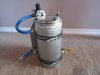
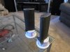
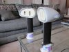
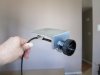
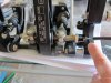
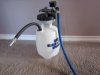
I converted a garden sprayer to a brake pressure bleeder. Mounted to the top is a mini regulator preset to about 10psi.

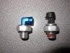
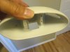
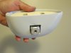
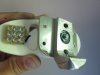
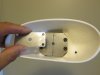
I bought a spare Tilton brake reservoir cap ($5) and converted it be used with the homemade pressure bleeder.
Here is the part number...Tilton Replacement Master Cylinder Caps 74-207 - Free Shipping on Orders Over $99 at Summit Racing

Or you can buy a premade one from Motive Products.
Here is the part number...1112 Tilton Round Reservoir Adapter

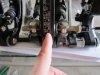
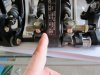
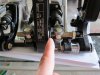
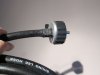
Here is a picture of my homemade cap adapter.
 

Attachments

  • 012_zpsg9gldoav.jpg
    012_zpsg9gldoav.jpg
    102.7 KB · Views: 196
  • 013_zpstwneyyom.jpg
    013_zpstwneyyom.jpg
    63.3 KB · Views: 221
Last edited:

Ken Roberts

Supporter
Next up I made my own engine oil preluber. It holds about 5 liters of oil. Mounted to the back of the aluminum cylinder is a regulator set to about 30psi. There is a fitting just behind the alternator (in the low mounted position) that is ideal for prelubing. The alternator needs to be removed to access it unfortunately but well worth it.
 

Attachments

  • 010_zps8j13ns8z.jpg
    010_zps8j13ns8z.jpg
    108.5 KB · Views: 219
Last edited:

Ken Roberts

Supporter
You can simply repurpose a LS engine oil sender to be used as the prelubing fitting for the block. You simply gut it and tap it for a small fitting as seen in the following picture.
 

Attachments

  • 017_zpspoagwx8e.jpg
    017_zpspoagwx8e.jpg
    171.7 KB · Views: 229
Last edited:
Thanks for the pics Ken. Now the more I look at that peddle assem. the more I'm amazed I am. That a work of art. Once again nice work...
 

Ken Roberts

Supporter
Thanks Matt! The planning of it was the most difficult. It was all cut by hand from pieces of angled aluminum. The only tools used were a reciprocating saw, die grinder, drill press and a stand mounted belt sander. If you look closely you can see that it was cobbled together. If I construct one more for a future GT-R build I'll make it a little bit prettier.....lol
 
Last edited:

Ken Roberts

Supporter
Here is a link to some cool carbon fiber side mirrors that mount on the horizontal part of the doors. At $400 a pair they are expensive but they have carbon fiber aero stems too. The model is called "Super Club Elliptical" with aero stems.

Race Mirrors: Club International designed for endurance


I'm going to change the round carbon fiber stems on my side mirrors to some streamline tube stems. You can buy the chromoly aero tubing at Aircraft Spruce.

4130 STREAMLINE TUBING from Aircraft Spruce
 

Attachments

  • Super_CES_zpspapkhapo.jpg
    Super_CES_zpspapkhapo.jpg
    125 KB · Views: 265
Last edited:
Ken,

I'm just catching up on your build.

The GM OEM PS delete hardware was a great find.

Your pedal assy is very creative.

You mentioned cruise control. How are you doing that?
 

Ken Roberts

Supporter
Hi Bill. First off ....your interior is outstanding. I'll be looking at the pictures many times to get ideas for finishing mine when the time comes. Thanks for sharing.

My cruise control is controlled from the C6 Corvette body control module (BCM).

Here is a system that can be used with the LS3 engine wiring. Their website doesn't give any details but I've read of a few builders on LS1tech that have used it.

http://www.spankysrodshop.net/

Here is a brief discussion about it from one user.

http://ls1tech.com/forums/generation-iv-external-engine/1490791-ls3-cruise-control-dbw-58x.html
 
Last edited:
Here are a couple pictures of Frans mirrors he sells I modified to work off the front fender. You can see out of them also plus they have the blinkers on there already and are less money. Didnt take much to cut and put the inserts in that are supplied with the mirror. Plus you were talking about brake bleeding, I just put a fitting in the cap of the reservoir and put a air regulator with about 3-5 psi of air, then you can loosen up each bleeder and let it bleed itself out, then just plug the hole in the cap. I used push in fittings so just used a 1/4 pin to block the hole. Did the same for the clutch also, just use 1 cap, and switch them as needed. Just the way I did it tho, been using that system with all my builds, I'm here alone so this makes it 1 man operation.
 

Attachments

  • SAM_0027.jpg
    SAM_0027.jpg
    126.5 KB · Views: 430
  • SAM_0026.jpg
    SAM_0026.jpg
    124.4 KB · Views: 381
Last edited:

Ken Roberts

Supporter
I built the new mirror stems today. They will be going out shortly with other items I have ready for tig welding. My friend Vinnie at Pipedream welding does fantastic work. I bought the aero tubing from Aircraft Spruce.

4130 STREAMLINE TUBING from Aircraft Spruce
 

Attachments

  • 004_zpsdgq3aovp.jpg
    004_zpsdgq3aovp.jpg
    86.4 KB · Views: 235
Last edited:

Ken Roberts

Supporter
The fabrication of the aero stem mirrors is done. I still need to construct the reinforcement plates for the underside of the doors. Todays job is to mount them to the doors. Then disassemble for tig welding and powder coating.

These are definitely not light. The mirror housing are thick and heavy and the aero stems and bases are steel. This is more for street use. Rugged and can take a light hit.
 

Attachments

  • 003_zpsvniqtile.jpg
    003_zpsvniqtile.jpg
    109.4 KB · Views: 246
Last edited:

Ken Roberts

Supporter
Here is a bottom picture. The aero stem shaft mounts to the back of the rectangular steel plate inside the mirror. The mirror housing is then opened up to allow it to protrude without touching.
 

Attachments

  • 001_zpsqd6vh8i2.jpg
    001_zpsqd6vh8i2.jpg
    78.4 KB · Views: 224
  • 002_zpsvhj54hk5.jpg
    002_zpsvhj54hk5.jpg
    67.3 KB · Views: 217
  • 003_zpsoldemdoa.jpg
    003_zpsoldemdoa.jpg
    60.4 KB · Views: 218
  • 006_zpsspeemoc2.jpg
    006_zpsspeemoc2.jpg
    64.9 KB · Views: 214
Last edited:

Ken Roberts

Supporter
I'm currently working on the brake bias adjuster. Here is a picture of the bracket under construction. This is the Tilton billet remote bias adjuster.
 

Attachments

  • 004_zps23js5fh8.jpg
    004_zps23js5fh8.jpg
    58.6 KB · Views: 214
Last edited:

Ken Roberts

Supporter
The first picture shows where the other end of the cable mounts to on the pedal assembly. My finger is pointing to where it attaches with a set screw on the right end of the threaded rod.
 

Attachments

  • 005_zpsvfxb1zqo.jpg
    005_zpsvfxb1zqo.jpg
    101.8 KB · Views: 211
Last edited:

Ken Roberts

Supporter
This picture shows the position of the balance point that you want to start with. My finger is showing that I have the balance point directly in the middle. This would be for a 50/50 brake bias. I took measurements with a thin ruler.

To adjust the balance point you simply spin the threaded rod. Looking at the threaded rod from the right side. Clockwise moves the balance to the left. Counter clockwise moves the balance to the right. My left master cylinder is for rear braking and the right one is for front braking.
 

Attachments

  • 007_zpsro0yr7dm.jpg
    007_zpsro0yr7dm.jpg
    95.2 KB · Views: 221
Last edited:

Ken Roberts

Supporter
In this picture you can see that I'm pointing to the left side of the balance point. My larger master cylinder (7/8") is in the middle position. This master cylinder feeds the rear brakes. Having the balance point moved to the left will now give you more bias to the rear brakes. Adjusting the remote wheel in a clockwise motion will adjust the threaded rod so that the balance point will be favoring the rear brakes.
 

Attachments

  • 008_zpsqp4dz0pq.jpg
    008_zpsqp4dz0pq.jpg
    94.3 KB · Views: 208
Last edited:

Ken Roberts

Supporter
In this picture I'm pointing to the right side. My front brakes are hooked up to this master cylinder (3/4"). Moving the balance point to this side will now favor the front brakes.
 

Attachments

  • 009_zpsqrykao9u.jpg
    009_zpsqrykao9u.jpg
    97.2 KB · Views: 224
Last edited:

Ken Roberts

Supporter
Start with 50/50 and go from there. Perhaps some SLC owners can report what they have found as the ideal balance for their cars. Anyone???

This picture is showing the jam nut that gets removed if you are using the remote bias adjuster. If not using the remote wheel than you simply thread the jam nut on (without turning the threaded rod mind you) all the way till it jams up against the barrel nut.
 

Attachments

  • 014_zpsbax9o0er.jpg
    014_zpsbax9o0er.jpg
    94.6 KB · Views: 221
Last edited:

Ken Roberts

Supporter
The chart included with the billet wheel mentions that every 360 degree spin of the wheel (or threaded rod) moves the bias just under 2 degrees. So if you want a 55/45 rear brake bias you would start at the middle balance position and then spin the wheel approx. 2 1/2 times clockwise. This will move the balance point to the left of center slightly.

In a separate chart it also mentions that every 1/8" inch of pivot movement equals 5 degrees of bias adjustment.

So spinning the wheel or threaded rod approximately 2 1/2 times will move the pivot point 1/8" or 5 degrees.
 

Ken Roberts

Supporter
If you want to be "dead nuts" accurate with your starting position of 50/50 then use a small ruler as in the following two pictures. Adjust the threaded rod till both measurements are equal.
 

Attachments

  • 011_zpsorj5fgcq.jpg
    011_zpsorj5fgcq.jpg
    84 KB · Views: 227
  • 012_zpsh0lp3spk.jpg
    012_zpsh0lp3spk.jpg
    93.5 KB · Views: 228
Last edited:
Back
Top