Ken's SLC build thread

Ken Roberts

Supporter
The SuperLite emblems have arrived. What do you think?
 

Attachments

  • IMG_1607.JPG
    IMG_1607.JPG
    137.2 KB · Views: 546
  • IMG_1614.JPG
    IMG_1614.JPG
    108.8 KB · Views: 522
Last edited:

Ken Roberts

Supporter
Last edited:

Ken Roberts

Supporter
While we are on the subject of A/C mounts for the SD7 compressor it's worth noting that Holley has a great setup now. It's very rugged and of OEM quality and style. It places the furthest part of the compressor pulley 11 1/4" from the crank bolt centerline. The Dirty Dingo mount is still the tightest at 10 5/8" from the furthest part out of the pulley to the crank bolt centerline.

Holley 20-159 Low LS Accessory Drive Bracket - Passenger's Side A/C Bracket


Both of these setups use the belt tensioner I mentioned in the previous post.
 
Last edited:
That Holley AC bracket is a great find, would have saved me untold hours. If I eject another AC belt I'll be looking into this part as it has a spring loaded tensioner.
Needs to be on the Wiki.

Those emblems are looking good, can't wait to see the hood emblem in place.
 

Ken Roberts

Supporter
Just a heads up for all the builders. The SD7 compressor isn't designed for high rpm use when the clutch is engaged (A/C on). A RPM switch must be used and set at something like 4500rpm for disengagement. Some of the early builders with the GTMs reported that the compressors self destruct at higher rpms if engaged.

There are many RPM based switches available that tap into a ignition coil wire. Lots are used for the nitrous crowd. You can also tap into the t body wiring for a signal based on throttle position.

There is lots of info on the SLC Wiki about this.
 
Last edited:

Ken Roberts

Supporter
I took the 2002 Camaro fuel pump module out of the tank for the last time to finish the mods to it. Earlier in the build I upgraded the fuel pump and wiring in the module to a Walbro 255 and heavier gauge wiring. I'm using a C5 Corvette fuel filter/regulator so I will not be using the regulator built into the module. It is replaceable so I removed it. I was left with the plastic housing still remaining. The return fuel to the module will just exit this black plastic housing now and spray randomly inside the bucket and tank now instead of directing the stream down into the bucket as designed to aid in keeping the bucket full of fuel all the time. I was able to completely remove it and attach a nylon flex tube to the remaining nipple at the underside of the top portion of the module. Now it directs the returning fuel stream in a OEM fashion and looks like it never had a built in regulator to start with.

The first picture shows the gutted and removed black plastic regulator housing. The second picture shows the flex tube installed with a Oetiker clamp to the remaining nipple at the top underside housing.
 

Attachments

  • IMG_1625.JPG
    IMG_1625.JPG
    94 KB · Views: 422
  • IMG_1618.JPG
    IMG_1618.JPG
    86.7 KB · Views: 455

Ken Roberts

Supporter
A little bit of trivia about modern fuel pump modules. Long gone are the days when the saying you should never let the fuel get below a 1/4 tank or the fuel pump will be uncovered. The first picture shows the pen pointing to a small brass nipple at the top of the fuel pump which sits in the bucket of the module. The second picture shows the pen pointing to a small diameter tube that connects this nipple to a mini jet pump located in the bottom of the bucket. As long as the pump is running fuel will always be sucked into the module bucket from the bottom of the tank via the jet pump and kept full and actually overflowing. When the pump is shut off the bucket is still kept full with a one way valve. Unused fuel from the regulator is also returned to the bucket as shown in the previous post. All of this helps keep the bucket full during demanding times. The only time the fuel pump will be uncovered in the bucket is just before it runs dry from not being able to suck fuel up from the bottom of the tank.
 

Attachments

  • IMG_1626.JPG
    IMG_1626.JPG
    95 KB · Views: 507
  • IMG_1628.JPG
    IMG_1628.JPG
    93.7 KB · Views: 577
Last edited:

Brian Kissel

Staff member
Admin
Lifetime Supporter
Hi Ken,

Thanks for the Ricardo starter motor connector info. I bought a few from this seller after your fit confirmation. I was able to get them for $8.00 each.

THANKS AGAIN !!
Regards Brian
 

Ken Roberts

Supporter
Hi Ken,

Thanks for the Ricardo starter motor connector info. I bought a few from this seller after your fit confirmation. I was able to get them for $8.00 each.

THANKS AGAIN !!
Regards Brian

I'm looking for a second Ricardo now for my LS9 engine build if you happen to know of any spare ones available.
 

Ken Roberts

Supporter
I cut out the frame for the bulkhead window this week. It was hand formed from a 3/8" thick 12"x24" sheet of 6061 aluminum. I made a tunnel on the other side of the frame that will get trimmed back to the final interior piece. It's twice as deep as it needs to be. I just wanted to make sure I didn't F-up on the depth. I'm glad to see this part finally nearing completion.
 

Attachments

  • IMG_1655.JPG
    IMG_1655.JPG
    117.2 KB · Views: 520
  • IMG_1656.JPG
    IMG_1656.JPG
    160.7 KB · Views: 583
Last edited:

Ken Roberts

Supporter
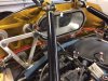
Starting to map out my BMW MK60 ABS brake install.

This system was factory installed on 2003 to 2006 BMW M3 cars. It uses 4 active speed sensors, front and rear brake pressure sensors/transducers, steering wheel angle sensor and a yaw rate sensor. The ECM for the system is mounted to the pump. It is very popular due to it's stand alone capability.
Incorporating the yaw and steering angle sensors gives it dynamic stability control.

Here are the OEM BMW part numbers:

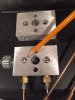
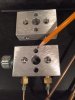
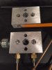
brake pressure sensors-#34521164458 (2 required)
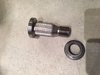
yaw rate (DSC Sensor)-#34526764018
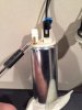
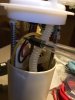
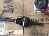
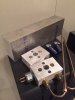
ABS pump/ECM-#34512282250
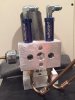
active wheel speed sensors F right #34526792896
f left #34526792897
rear l/r #34526752683

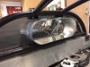
The ABS pump/ecm and yaw rate sensor will be used and the pressure sensors and wheel speed sensors will be new. The wiring harness comes with a steering position sensor I believe. I might try and use the sensor already installed on the XLR column if possible.

The wiring harness can be purchased from 3DM Motorsports and is made by Racing Harness Technologies. (Doug Wardell). They can tailor it to your application.
MK60 Motorsport ABS – Tagged "MK60 Motorsport ABS_Universal Kits" – 3DM Motorsport

Category:MK60 Motorsport ABS - 3DM Motorsport Info

I'm most likely going to only use the rear BMW style of active wheel sensors. They look more user friendly in shape.
 
Last edited:

Ken Roberts

Supporter
I have RaceLogic traction control with the passive sensors currently mounted. My front hubs are the C6 30 spline X Trackers hubs with passive sensors. The rear has tone rings and passive sensors installed at the outboard end of the axle shaft (930 joints). I can add another set of tone rings at the inboard side and two of the BMW active sensors or I can add the C6 33 spline X Tracker hubs in the back with the active sensors if I elect to upgrade my hubs and uprights. If you use the C7 hubs please note that they do not have wheel sensors incorporated into them.

In the front I have a unique solution to add tone rings and active sensors. It will unfortunately add a bit of weight and I'm OK with that. I purchased a used set of rear c5/C6 axles with 30 splines for $100 shipped on E Bay. I just want the stub shafts so I cut the rest off.

The first picture shows the stubshaft being cutoff the stock C6 Corvette axle with a angle grinder using a thin abrasive cutoff blade.

The second picture shows the additional cuts (getting it ready for sending to the machine shop). The goal is to have the machine shop do the least amount of work to keep the cost down....lol
Next is to hollow/drill out the stub shaft (this is where the machine shop comes in) to make it as light as possible. It will actually be mounted/bolted in the hub and spin a tone ring that will be welded in place and sticking out the backside of the upright. One of the BMW active wheel speed sensors will be fastened to a bracket I come up with.
So in the end I will have both active and passive sensors at each wheel position. If I would have known this years ago I would have just bought the RaceLogic traction control used for active sensors instead. I have a second Racelogic setup (in waiting) for my next car build that uses passive sensors as well.

The tone rings from the Driveshaft Shop (for the rear axles) have a 48 tooth count. Dorman sells a 48 tooth tone ring #917-552 that was used on Toyota Camry from 02 to 06. I will use them for the front axles.
 

Attachments

  • IMG_2244.JPG
    IMG_2244.JPG
    917.3 KB · Views: 378
  • IMG_2259.JPG
    IMG_2259.JPG
    721.5 KB · Views: 411
Last edited:

Ken Roberts

Supporter
The BMW brake pressure sensors use a M12 x 1 pitch thread. I'm making two of the needed mounting blocks, one for my current car and one for my next car.
The first picture shows what each block will look like. The idea is to install the sensors right after the master cylinders. One sensor to monitor the rear master cylinder pressure and one to monitor the front master cylinder pressure. Scott Swartz has a great setup where his sensors mount directly to the more expensive Tilton master cylinders. His sensors use 1/8" NPT so adapters were installed to go from 3AN to 1/8" NPT. Unfortunately that idea won't work with the larger M12 thread size fittings on the BMW sensors.
Installing the ABS system will require all of the older style brake lines inside the front bulkhead to be removed/scrapped. This was a good time to mount the 2lb residual pressure valves to the top of the blocks for simplicity sake. Also brake light switches can be mounted in each "side" 1/8" NPT threaded holes. One for the brake lights and one for the ABS brake signal. My car doesn't require them as I'm using rotating sensors at the clutch and brake pedal assembly. In my case 1/8"NPT pipe plugs will be installed in both side threaded holes. I'll just tap into my brake light power wire and use a 5-pin relay
 

Attachments

  • IMG_1807.JPG
    IMG_1807.JPG
    112.6 KB · Views: 466
Last edited:

Ken Roberts

Supporter
Very cool, Ken! Curious, what tone ring did you use on the rear? I'm looking for a good option there :)

I used the tone rings from The Driveshaft Shop and available thru Fran. They are drop shipped from the DriveShaft Shop I believe. They have a 48 tooth count.
 
Last edited:

Ken Roberts

Supporter
The outboard holes as shown with the pencil will be tapped to M12x1 once I receive the special tap. These are the holes for the brake pressure sensors. They are straight tap threads so the sealing action will take place at the copper crush washer.
 

Attachments

  • IMG_1808.JPG
    IMG_1808.JPG
    116.5 KB · Views: 435
Last edited:

Ken Roberts

Supporter
The two holes in the middle....one at 12 o'clock (as pointed to with the pencil) and one at 6 o'clock are for the mounting studs. The larger hole in the middle is just to take some weight away.
 

Attachments

  • IMG_1809.JPG
    IMG_1809.JPG
    117.5 KB · Views: 477

Ken Roberts

Supporter
Six 1/8" NPT tapped holes are placed around the perimeter. The 1/8" NPT holes on either side can be used for either a brake light switch or brake pressure sensors with 1/8" NPT fittings as used with Motec or AIM dataloggiers. The factory supplied brake light switch should be discarded as they are not low enough in pressure to trigger your brake lights early enough for street use. The ABS system needs a signal from the brake lights to signal brake activation. A 5pin relay will need to be used because the circuit must go to ground with the pedal not pressed and open when pressed.
 

Attachments

  • IMG_1810.JPG
    IMG_1810.JPG
    112.7 KB · Views: 476

Ken Roberts

Supporter
These two blocks were simply cut and shaped with a reciprocating saw and dressed on a stationary belt sander. The holes were drilled and tapped with a bench mounted drill press. Here is a picture of the raw block I just happened to have. No fancy machine shop equipment was used. Attention to detail in the layout and marking off is the most important part. You want all the passages to intersect correctly.

Remember only one block is required. I built two in case I add ABS to my next car.
 

Attachments

  • IMG_1811.JPG
    IMG_1811.JPG
    102.9 KB · Views: 440
Back
Top