
- Forums
- GT40 Replica Manufacturers' Corner
- RCR Forum - RCR40/SLC/917/Superlite Aero
- The SLC Clubhouse
You are using an out of date browser. It may not display this or other websites correctly.
You should upgrade or use an alternative browser.
You should upgrade or use an alternative browser.
Ken's SLC build thread
- Thread starter KENS80V
- Start date
Ken Roberts
Supporter
Here are the part numbers for new locks and outer door handles. I later took the locks to a locksmith to have both sides keyed alike.
 .
.
Howard Jones
Supporter
How about thread the four holes. Then make a steel 90 degree flange, mount it on top with four holes for the steering box and a couple to bolt the other side to the firewall with through bolts and nuts. Simple and easy.
Ken Roberts
Supporter
Work has begun on the parking brake module for the GT-R. I plan to mount it to the left of the drivers seat so it must be tall and narrow. I want to make it mount as a module just in case I want to remove it for track only duty. It has a momentary switch incorporated for the C6 Corvette ZR1 electrical system. A few functions with the Tech 2 scanner can't be performed unless it detects that the parking brake is applied. There is a fuel pump inertia switch mounted at the front for the fuel pump relay. I might leave it open "as is" ....kinda looks cool like the Pagani Huayra shifter.
The two halves are cut out from a one foot piece of 2" x 5"rectangular steel tubing. A zip blade on an angle grinder, file and die grinder were the only tools used. The parts are almost ready for welding.

The two halves are cut out from a one foot piece of 2" x 5"rectangular steel tubing. A zip blade on an angle grinder, file and die grinder were the only tools used. The parts are almost ready for welding.
Last edited:
Ken Roberts
Supporter
Parts for the parking brake:
Hand brake lever- http://www.controlcables.com/parking-brake-controls/?sort=featured&page=1
Cables- https://www.summitracing.com/parts/lok-ec-80fu/
Fuel cutoff intertia switch- https://www.summitracing.com/parts/smp-fv7/
Calipers- https://ipsco.org/newsite/product/ips080-xxx-mech-parking-brake-caliper-options/
Last edited:
Ken Roberts
Supporter
Good deal on a used accusump here:
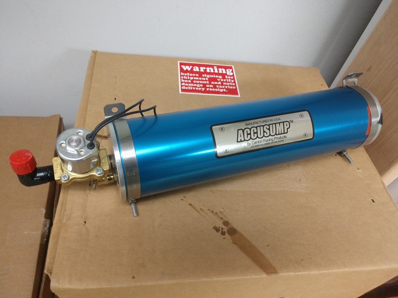
Accusump with valve - CorvetteForum - Chevrolet Corvette Forum Discussion
Autocrossing & Roadracing Classifieds - Accusump with valve - SOLD. 3qt Accusump with the basic electric valve. Used in my standing mile car so it has very little run time compared to what you guys do! Engine came out perfectly clean and was untouched other that a drysump conversion (you may...
www.corvetteforum.com
Looked like a great deal. Unfortunately it was sold when I went to check it out.
Thanks for posting it Ken.
Regards Brian
Thanks for posting it Ken.
Regards Brian
Ken Roberts
Supporter
Winding down the mirror construction for the future GT-R. I want to mount the passenger mirror on the door instead of being forward on the fender like the Robertson Racing cars. This meant changing the housing "face" to a steeper angle. I copied the angle on my Camry for reference. I intentionally broke the mirror glass. This makes it easier for fit up and final assembly after paint. A pair of quality replacement mirror glass are $30 (Burko #4084 and #5163) I installed two 9" long 3/8" diam threaded rods in the stem for strength. I then poured in 2 part epoxy to encapsulate the rods. There is also a stainless tube installed for the wiring. These mirrors are very strong now. The only thing left to do is a bit of body filler on the inside of the mirror housing to hide the raw fiberglass look. This will give it a more OEM look.
The white epoxy surrounding the nuts at the bottom of the door mount was to aid in keeping the liquid two part encapsulating epoxy from running out. It's very expensive stuff. Same stuff used for making river tables.


The white epoxy surrounding the nuts at the bottom of the door mount was to aid in keeping the liquid two part encapsulating epoxy from running out. It's very expensive stuff. Same stuff used for making river tables.
Last edited:
Ken Roberts
Supporter
I'm using a stock Impala mirror switch. I made a flange for attaching the switch behind a panel. The flange gets secured to the switch by epoxying it on from the backside. Now the switch can be secured to the backside of a panel with a bead of silicone. For the front side a dress plate was made and painted black and also gets secured with a thin bead of silicone.
Here are the PDF templates (remember to set your printer to 100%). The second template also doubles as the hole cutout size in the panel.


Here are the PDF templates (remember to set your printer to 100%). The second template also doubles as the hole cutout size in the panel.
Attachments
Last edited:
Ken Roberts
Supporter
Starting to work on the doors. Look at the butchered door hinge mount area cut out by the factory. Does anyone have a template for the cutout area? I'm going to put 1/8"steel plates on both sides epoxied and fastened together. Then cutout new holes/slot.

Ken Roberts
Supporter
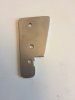
Test fitting 1/8" thick steel backing plates for the bearclaw latches. I can easily see the three mounting holes in the fiberglass getting worn over time. That and the bolts backing out from the continuous shock put on the assembly when the door closes. A bunch of small holes will be drilled in the plate to aid with the shear strength once epoxied in place. The goal is to help retain the alignment of the doors over time.
I scanned the template if anyone wants to copy the design.

I scanned the template if anyone wants to copy the design.
Last edited:
Joel K
Supporter
Test fitting 1/8" thick steel backing plates for the bearclaw latches. I can easily see the the three mounting holes in the fiberglass getting worn over time. That and the bolts backing out from the continuous shock put on the assembly when the door closes. A bunch of small holes will be drilled in the plate to aid with the shear strength once epoxied in place. The goal is to help retain the alignment of the doors over time.
I scanned the template if anyone wants to copy the design.
View attachment 103728
Hi Ken, looks like a good approach. I’d like a copy of the template when you have a chance. Thanks!
Ken Roberts
Supporter
Ken Roberts
Supporter
Here is a template for a trick Graziano speed signal sensor mount (Remember to set your printer to 100%). Needed for a ECM/speedo signal. You can purchase the 48t reluctor wheel from Fran and mount it on the driverside inboard CV joint. This plate will give you a nice place to mount your sensor. I mounted a ABS active sensor and a passive sensor for the ECM to this mount (see 4th picture).
Attachments
Last edited:
Ken Roberts
Supporter
The bearclaw latch is now connected to the outer door handle with a flexible cable. A steel rod connects the bearclaw latch to the inner door handle. The outer door handle lock mechanism works perfectly. No grinding was needed in my application. Not even with the addition of the reinforcing plate at the bearclaw latch. Next up is to buy a couple of momentary "pull" solenoids with remotes. They will connect (in parallel) to the steel rods going to the inner door handles. The outer door handles will remain in the locked position for the most part (similar to shaved door handles)(door poppers won't be needed as I still have outer door handles). The only time I'll need to use the lock cylinder is if the solenoids fail or I lose electrical power. Then it's a matter of unlocking the outer door and using the handle to unlock the door. I wouldn't advice doing this without the outer door lock cylinders operational unless you have an emergency way of activating the latches with a loss of electrical power.
The only problem with this approach is if you leave the door key and door opener fob in the car and close the door. I have keyless starting so for the most part the fob and key will be in my pocket. Please comment if you can think of any problems with this idea!

 www.speedwaymotors.com

The only problem with this approach is if you leave the door key and door opener fob in the car and close the door. I have keyless starting so for the most part the fob and key will be in my pocket. Please comment if you can think of any problems with this idea!
SPAL SHAVED-40 Basic Shaved Door Handle Remote Entry Kit
If your street rod doesn't have this SPAL shaved door handle remote entry system, you don't know what you're missing. You can add another solenoid and relay for your trunk if desired. Basic Kit includes: Two massive 40 lb. pull solenoids Two 4-button transmitters One 7-channel receiver Hardware...
Last edited:
Ken Roberts
Supporter
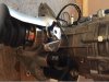
I added a steel plate to the inside of the door at upper hinge mount. The pocket in that area was perfect for bonding in a plate. I drilled out the 1/4" coarse threads on the hinge and upgraded to 5/16" fine thread.
The problem I found was that there is actually two panels the fasteners were clamping. My panels had voids where the glue wasn't present and the fasteners were fracturing the inner panel as I snugged up the bolts. This solution spreads out the clamping force and provides better shear strength.

The problem I found was that there is actually two panels the fasteners were clamping. My panels had voids where the glue wasn't present and the fasteners were fracturing the inner panel as I snugged up the bolts. This solution spreads out the clamping force and provides better shear strength.
Last edited:
Ken,
I have been considering electric solenoid (or pneumatic) entry in my build as well. My purpose though is to get rid of the handles and smooth that area over. Lack of emergency entrance is what is stopping me from going this route. The best idea I have so far is to remove the windows for emergency entry in the case of an electronic or pneumatic failure.
I have been considering electric solenoid (or pneumatic) entry in my build as well. My purpose though is to get rid of the handles and smooth that area over. Lack of emergency entrance is what is stopping me from going this route. The best idea I have so far is to remove the windows for emergency entry in the case of an electronic or pneumatic failure.
Ken Roberts
Supporter
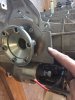
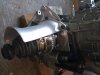
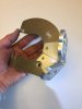
Check your outer door handles first if wanting to do the lock cylinder addition/modification. My original ones had that area shaved off for easier installation by the factory. My pencil is pointed to the area cutoff. If yours are similar than you'll need to buy new handles.
See post #883 for an idea of what that area should look like. It must have that horizontal wire going around the circumference. It's needed to retain the separate lock cylinder and can't be purchased by itself.

See post #883 for an idea of what that area should look like. It must have that horizontal wire going around the circumference. It's needed to retain the separate lock cylinder and can't be purchased by itself.
Last edited:
Similar threads
- Replies
- 5
- Views
- 1K
- Replies
- 1
- Views
- 2K