KVA / SGT build

Udo

Supporter
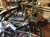
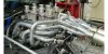
Hi Dan, some folks say that the crossover provides increased efficiency, other deny that. There are a lot of opinions also here in gt40s. I looked at different exhaust types before I started, and my benchmark is shown in the attachment. By the way, it was really exciting and fun to work on it, and straightforward tubes as in your GTD are unachieveable for me, working with standard bent tubes (I used 15, 30, 45, 60 and 90 degree pre-bend stainless).

Udo
 

Attachments

  • C0A6829F-CB9C-447C-A210-29A9FD3B54B1.jpeg
    C0A6829F-CB9C-447C-A210-29A9FD3B54B1.jpeg
    448.3 KB · Views: 881

Udo

Supporter
After having the gear cable attached to the gearbox, next step was to do the same on the shifter. I detached the cable from the car and mounted it to the shifter, fig 1. Luckily, I measured the cable lenght correctly, and it fits perfectly into the car, fig 2 (see also my Ford-logo equipped wooden knob on the shifter, looks great). The link to the gearbox was last thing to do, fig 3, and for the time being, gear shifter got the status „pre-installed“. To finish, I believe the clutch cylinder needs to work first - next job already defined .

More to follow,

Udo
 

Attachments

  • AE0B7A15-D2EE-43CB-B05E-D39A0841A718.jpeg
    AE0B7A15-D2EE-43CB-B05E-D39A0841A718.jpeg
    463.8 KB · Views: 695
  • 70B440DA-802C-4AE5-9539-8824057D270F.jpeg
    70B440DA-802C-4AE5-9539-8824057D270F.jpeg
    303.9 KB · Views: 676
  • 4BF5ED93-D38D-4CA7-8314-9D31BAD5E353.jpeg
    4BF5ED93-D38D-4CA7-8314-9D31BAD5E353.jpeg
    500 KB · Views: 653

Udo

Supporter
After checking the gear shifter mounting situation a second time, I felt that a reinforcement was worth to install, fig 1, and the stiffness advantage afterwards was impressive enough to keep this solution. Some more residual work to be done, e.g. the cylinder head ventilation into the catch tank, fig 2, which has now more distance to the exhaust pipes. Last thing was to take out some weight from my silencer mounting bracket - some 13 mm drills, and the part lost some percent of its former weight (I didn‘t measure in order to avoid any frustration ).

More to follow,

Udo
 

Attachments

  • ADDF70E8-D27F-462F-BDFA-18ADE11CBDFA.jpeg
    ADDF70E8-D27F-462F-BDFA-18ADE11CBDFA.jpeg
    452.8 KB · Views: 704
  • 40D53F50-45D3-4CB4-8A39-F8B3752A963F.jpeg
    40D53F50-45D3-4CB4-8A39-F8B3752A963F.jpeg
    579.1 KB · Views: 614
  • 5CD223BF-A0B6-47D9-9DB9-63C8E1B10DAA.jpeg
    5CD223BF-A0B6-47D9-9DB9-63C8E1B10DAA.jpeg
    635 KB · Views: 615

Udo

Supporter
My beetle needed some attention yesterday, so only things happened on the 40 were installation of clutch cylinder and throttle cable. Really like the bordering tool for the clutch line, fig 1, and after a while, the Audi connecting pipe got mounted to the gearbox and the clutch line (connector on the right in fig 2). Finally, I installed the throttle cable, no issues here, big surprise .

More to follow,

Udo
 

Attachments

  • D1CF382D-80C9-4435-B566-410EF35CBED8.jpeg
    D1CF382D-80C9-4435-B566-410EF35CBED8.jpeg
    492 KB · Views: 658
  • 51F59844-DE34-45A8-83C1-CB9EBD20B188.jpeg
    51F59844-DE34-45A8-83C1-CB9EBD20B188.jpeg
    440.6 KB · Views: 657

Udo

Supporter
Some further electrical work done - engine cable harness pre-installed, fig 1. The control unit behind co-drivers seat is also attached, fig 2, a important step forward to run the engine.

Also important: Exhaust came back from TIG welding, I „just“ need to finish it over the next weeks.

More to follow,

Udo
 

Attachments

  • 559704BC-F92B-4874-8001-CF41144EC18B.jpeg
    559704BC-F92B-4874-8001-CF41144EC18B.jpeg
    540.1 KB · Views: 597
  • 390F2AF6-B5FE-49DE-9328-0EAD3897EF81.jpeg
    390F2AF6-B5FE-49DE-9328-0EAD3897EF81.jpeg
    342.6 KB · Views: 547

NickD

Supporter
Great work Udo, looks like your making really good progress. I’m still messing around with my engine mounts as i’m Lowering the engine a full 2 inches.

Nick.
 

Udo

Supporter
Last weekends LMC2018 was naturally highly inspiring (including three laps with my Cobra, really unique), so I got well motivated back to the workshop, even if the next jobs were not that promising: finishing of the exhaust pipe weld seams. It took a while, and after 50% of grinding work done, I needed some change, fig 1. Remaining wireness harnessing was the ideal one, since the cable from control unit to battery in the front of the car needed to be installed. Fig 2 shows the cables, to be mounted to my lightweight aluminum carrier plate behind the tank. Next week exhaust grinding again, I‘m seeking for motivation :pepper:

More to follow,

Udo
 

Attachments

  • A08EABFF-27C3-4118-9BA1-8EB56883D80B.jpeg
    A08EABFF-27C3-4118-9BA1-8EB56883D80B.jpeg
    508.5 KB · Views: 669
  • 647F3E2B-9B6D-4843-8E3D-DC67C1E14482.jpeg
    647F3E2B-9B6D-4843-8E3D-DC67C1E14482.jpeg
    475.6 KB · Views: 579
Last edited:

Udo

Supporter
Noticed a collision between hand brake linkage and water pipe, so needed to re-do some hoses. Fig 3 shows the current and hopefully final setup with a new 90 degree reducing adapter from 45 to 38 mm, including the also fitted V-belt. After some adjustment, activating of hand brake leads to almost parallel braking of rear wheels, nice and simple, fig 2.

Got the adaptor for the oxygen sensor last week, and mounted it to the 4-in-1, fig 1.

Awainting now the remaining TIG welded exhausts back in order to finish and mount them back into the vehicle. It‘s summer time, and things slow down a bit ...

More to follow,

Udo

3FF501F6-586D-448A-8C3B-4712D9BE3AF9.jpeg7B09BD9B-5590-4754-954F-6D66BF05F18A.jpeg47799116-2FD9-4E97-AB16-1FF47F35F650.jpeg
 

Udo

Supporter
After some days of welding, all exhaust pipes are ready in the meantime, same for the silencer to 4-in-1 connection. Since I am still not clear which surface finish I am going to use (every hint here is highly appreciated, I am looking for something that covers a few surface imperfections and looking forward to receive some feedback), re-assembly got started. I had some doubts about welding distortion, but this was only a very minor issue. Fig 2 shows the situation without silencers, fig 1 with them and with mounted oxygen sensor.

With the installed exhaust, I also could route the ignition wires, and decided to guide them over the valve covers, fig 3. This may not be the classical approach, but worked in my other V8 car for 25.000 km very well - never change a winning team ...

More to follow,

Udo

B9BADF10-94B2-489C-BB0F-A25A4ACFE186.jpeg
B4E43887-1821-4DE4-867D-70DDCC3EC268.jpeg
A1C8D0D7-AC33-49BC-B0E8-BFDC108FA5DF.jpeg
 
Last edited:

Udo

Supporter
Next steps to start the engine done yesterday: accelarator cable mounted, covered by 2.000 C heat protection hose, same for the lambda sensor cable - this should work (fig 1).

The oil and water temperatur gauges I purchased got manual sensors, and the lines from gauges to sensor are obviously quite sensitive. Fig 2 shows the back of the cockpit with the two lines, the successfully installed water sensor in fig 3. There is no picture of the oil sensor, since the threat in the engine for some reasons doesn‘t fit. Need to buy an adaptor today ...

More to follow,

Udo

F692698E-B25E-4154-A517-242E342A8EDC.jpeg
7C6D3273-6FC4-4AEF-81FC-E4EB1EB20428.jpeg
DEEE7FF0-FD7D-4332-931C-81561F06331E.jpeg
 

NickD

Supporter
Hi Udo, Looks like we are literally step in step with the builds. Hate to say but your home built exhaust is better than mine. Tried so hard to get it spot on but all I can say is its functional. Certainly not the prettiest but it will do for now. Have got one pipe done but another 7 lined up to grind the welds down. By far the worst part of the job ;-((. Have decided not to pay the high price for ceramic coatings but will instead opt for a good nickel coating (not shiny) that should prove lasting and easy on the eye ;-)
 

Attachments

  • CODyb2cwQn2ey5j%ivpYDA.jpg
    CODyb2cwQn2ey5j%ivpYDA.jpg
    613.3 KB · Views: 524
Hi Udo,
Nice to see some great progress. Your throttle bodies need swopping around so that the throttle position sensor is moved away from the exhaust, otherwise it won't last long!
Regards,
Andy
 

Udo

Supporter
Hi Udo,
Nice to see some great progress. Your throttle bodies need swopping around so that the throttle position sensor is moved away from the exhaust, otherwise it won't last long!
Regards,
Andy

Andy, thanks for the hint. I build a small bracket, attached the throttle cable, so distance to the exhaust should be ok. Cheers, Udo
1F1701B6-8932-4044-AB72-6BF60C403256.jpeg
 

Udo

Supporter
Besides routing of throttle cable, the rear clip needed some more material to be half way symmetric left and right. After four additional fibre maths and some days of curing, the loop of grinding and filler application can start again. Let the good times roll!
0A691B40-F5BF-4C47-8C58-FB8FB38994FA.jpeg


Oil temperature gauge got also assembled with the freshly delivered thread adaptor, so I had time to wotk on a proper fixing of the dipstick, which had no other attachment than the one in the oil pan. To avoid cracking due to vibrations, I build a simple bracket, bolted to exhaust flange no. 7:
B5BB91F2-BE9A-4EF3-A2D8-EEBAF719AC67.jpeg


Will order the main battery cable today, so first engine start gets closer ...

More to follow,

Udo
 

NickD

Supporter
Looking really good Udo. Your making great progress. I’m still grinding the exhaust welds down and making good. Everything is taking a little longer than expected now the nights are drawing in and temp has dropped a little. Keep the pics coming.
 

Udo

Supporter
Hi Nick, yes, at a certain point in time, grinding is just not more the fun part at all. But as you have spent some time on your exhaust build, you also will make the rest . Udo
 

Markus

SPRF40
Lifetime Supporter
Andy, thanks for the hint. I build a small bracket, attached the throttle cable, so distance to the exhaust should be ok. Cheers, Udo


Udo,
I think Andy was refering to TPS itself, you need at least some sort of heatshield between the sensor and the exhaust - there is a lot of heat - don't underestimate!!!! Moving the sensor to the front now might be the easier and better solution than searching a bug and changing later.
Don't ask why I know......
Markus
 

Udo

Supporter
To save the TPS from exhaust heat (took Markus’ and Andy’s hint serious), I build this cover with heat protection foil - hope that the adhesive will survive. Getting sensitive to this matter, I covered the lambda sensor cable also with heat protection foil:
478689B8-C475-42FA-869A-1629CAFD41DA.jpeg


Besides grinding of the rear clip, some further installation work done: throttle cable partly inside the cabin ...
65A5C0F8-D425-4490-B0C7-DF566565A50C.jpeg


... and starter cable also mounted:
E1FC85E3-C4F1-4822-A0BD-41F8CB04F26F.jpeg


Another step towards first engine start!

More to follow,

Udo
 
Back
Top