
You are using an out of date browser. It may not display this or other websites correctly.
You should upgrade or use an alternative browser.
You should upgrade or use an alternative browser.
LBC Build Log - Apex
- Thread starter LBCportagee
- Start date
Coolant tubing is tacked. Just need to get another argon bottle so we can purge and weld. We couldn't make a straight shot from the radiator because it's angled down. Then we needed to squeeze under the rack...that's why there's an "extra" 45'.


We need to lower the engine still which will affect the remaining tubing lengths. Tbd.
We need to lower the engine still which will affect the remaining tubing lengths. Tbd.
Howard Jones
Supporter
Get one of these and you can use one tank.
And don't forget to add a drain bung and plug at the low point in the system.
And don't forget to add a drain bung and plug at the low point in the system.
Inert Gas "Y" Valve Argon Western # 411 - Gas Welding Valves - Amazon.com
Inert Gas "Y" Valve Argon Western # 411 - Gas Welding Valves - Amazon.com
www.amazon.com
Get one of these and you can use one tank.
And don't forget to add a drain bung and plug at the low point in the system.
Inert Gas "Y" Valve Argon Western # 411 - Gas Welding Valves - Amazon.com
Inert Gas "Y" Valve Argon Western # 411 - Gas Welding Valves - Amazon.comwww.amazon.com
Thanks Howard. Those are definitely a good option and save's some space. I like having a spare tank so I can continue working when I replace the empty. I also had another cheap regulator that came with the welder and a spare hose.. So I just bought some cheap silicone plugs to make my own purges. 1/4 of the price for three times as many vs the welding brands. I just use sintered air fittings as the diffuser. Quick disconnects are nice too.
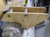
Getting started on lowering the engine and trans. Mostly planning so far. I'm going to move the attachment point of the motor mount forward of the cradle and remove the factory transaxle mount for a new one. The engine/Trans will be moved about 2-1/4" down, limited by the starter and a couple other places. Here's the mount I drew up that matches where I need it.

Started to machine the tube and bushings

Better look at bushings.

Started to machine the tube and bushings
Better look at bushings.
Took a little while to get things cut out and tacked. We tacked the motor mounts back to back before welding them to prevent warping the plates.

Prior to some paint. Need to machine a little more off the bushings after welding the tubes.

Next week hopefully we can cut the frame, motor & trans mounts off and then get the new trans mounts welded back on, otherwise I'll have to leave the engine hanging on my somewhat aging cherry picker. Slow progress as I'm really only getting about 4 hours a week at best on this.
Prior to some paint. Need to machine a little more off the bushings after welding the tubes.
Next week hopefully we can cut the frame, motor & trans mounts off and then get the new trans mounts welded back on, otherwise I'll have to leave the engine hanging on my somewhat aging cherry picker. Slow progress as I'm really only getting about 4 hours a week at best on this.
Got around to starting the process of lowering the engine. The trans mount is 90%. The take away here is our frame is so unsymmetrical (not a news flash), it was SUPER difficult to determine a proper alignment of the engine. Heres a before/after of trans mount. Superlite's mount is using a long bolt through an aluminum block. This cause they screwed up their measurement of where the engine would go and was their "fix".

And now about 2-1/4" lower. Which leaves about 1/2" clearance for starter.

And now about 2-1/4" lower. Which leaves about 1/2" clearance for starter.
I was sure to double check the starter cleared the frame when I lowered the engine. I seemed to have overlooked the alternator, not that it would have changed anything. Mocking up an alternator relocation bracket, I'll make of aluminum. This is really the only place it will fit. This pic also shows the motor mounts. I plan to reinforce the lower brackets some still.


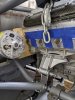
Got the radiator stainless tubing all welded and in. The 417 manifold and location of the water pump works out well with pretty straight shots. Gonna have to work around that alternator on the other side though.

Got the radiator stainless tubing all welded and in. The 417 manifold and location of the water pump works out well with pretty straight shots. Gonna have to work around that alternator on the other side though.
Attachments
I've been working on the brake and fuel system lines....lets just say I've had quit a few changes in direction and many purchased/returned fittings...and at least two hard lines flared without the fitting on....lol. I did manage to wrap up the alternator bracket finally. Plan on getting a laser belt alignment tool to get in dialed in.
Basically had to make these with hand tools...jig saw, router, carbide grinder...etc. My plasma cutter wouldn't get through the aluminum (at least with the incorrect orifice size it wouldn't). Hardest part was figuring out how to add the tensioner to the bracket.


Basically had to make these with hand tools...jig saw, router, carbide grinder...etc. My plasma cutter wouldn't get through the aluminum (at least with the incorrect orifice size it wouldn't). Hardest part was figuring out how to add the tensioner to the bracket.
Thanks, I hadn't considered that. I'll do that when I go back to recess the bolt holes. I think one or two heads may interfere with the belt just slightly. I also need to add a shallow channel on one bracket for the head gasket that protrudes from the side of the head. It prevents it from sitting completely flush, so I have not fully tightened it downNice job sneaking that tensioner in there.
Looks like you used a chambfer bit with bearing guide in a router. I've done the same and it works great. But the radius around the alternator fan might benefit from a much deeper chambfer to not impede airflow from the fan.
Last edited:
I've been looking for header options that will fit and aren't $3k. I was considering C8 manifolds with an LS flange (head). Slightly difficult because of how they transition from round primaries to oval ports. Would require some short tubing added to each primary for the area cut-off. Really considering this since I can take these off my C8 and get real headers for it. Win/Win.
But then I found Camaro headers that may work (in either direction) with a much easier modification of just clocking the Exhaust Flange. The key is they sweep forward first and end the collector well short of the block giving room to direct over axel etc. Could also Flip them over to face up.
There's some inexpensive ebay styles but kooks also makes a version if you want to pay x4.

Here's a gtm with them.

But then I found Camaro headers that may work (in either direction) with a much easier modification of just clocking the Exhaust Flange. The key is they sweep forward first and end the collector well short of the block giving room to direct over axel etc. Could also Flip them over to face up.
There's some inexpensive ebay styles but kooks also makes a version if you want to pay x4.
Here's a gtm with them.
I pulled the trigger. Bought these for $225.
.webp")
Basically been working on three things. I wanted to get the basics of the exhaust and intake routing done and start to attack some body work plans.
The cheap headers will work. They weren't back purged, but that's no surprise for the cost. The primaries were 1 7/8" which I wanted but the collector was to 2 1/2", so I will increase that to 3" with a transition cone. I cut off the header flange which pointed in wrong direction and got started with the v-bands. Added a O2 bung to the transition too.

I started putting together an x-pipe. Doing a splayed pipe and pretty happy with the fit-up given the cheapy harbor freight 4x6 bandsaw.

Got the basics of intake tubing mocked up, but won't be doing anything with this until I have the body attached. Also I decided to cut the rear body in two to create a removable clam. I decided against a hinge for the clam though. The Apex was designed for none of the rear body to be removable and that's just not going to work.

Lastly created some body alignment pins on the lathe. Just need to thread it now.

The cheap headers will work. They weren't back purged, but that's no surprise for the cost. The primaries were 1 7/8" which I wanted but the collector was to 2 1/2", so I will increase that to 3" with a transition cone. I cut off the header flange which pointed in wrong direction and got started with the v-bands. Added a O2 bung to the transition too.
I started putting together an x-pipe. Doing a splayed pipe and pretty happy with the fit-up given the cheapy harbor freight 4x6 bandsaw.
Got the basics of intake tubing mocked up, but won't be doing anything with this until I have the body attached. Also I decided to cut the rear body in two to create a removable clam. I decided against a hinge for the clam though. The Apex was designed for none of the rear body to be removable and that's just not going to work.
Lastly created some body alignment pins on the lathe. Just need to thread it now.
Ran out of Argon so started working on the front body. Again not meant to be taken off, but I need access to brake/battery etc. So we cut a removable hood.

I think we got really lucky with the placement of the radiator. Couldn't be tighter.

I think we got really lucky with the placement of the radiator. Couldn't be tighter.
Cut the hood opening and started duct
.jpg")
Made a bit of a miscalculation on the room I had to include a bend after the headers (because I added in the 2.5" to 3" cone transition). No biggie, just means I'm going to add the exhaust bellows further back at the x-pipe instead of directly behind the headers. I think that should be okay as I'm not going to have a connection to the actual chassis until after the bellows. The x-pipe will be supported above the transmission (connected/isolated to the trans). I have everything solid mounted (engine/trans), but I'm not sure about movement between engine and trans, or if they mostly move together.
Headers-->vband-->tubing back & joined to x-pipe (supported by trans)-->v-band--> bellow-->Mount to Chassis (isolated)

Headers-->vband-->tubing back & joined to x-pipe (supported by trans)-->v-band--> bellow-->Mount to Chassis (isolated)
Similar threads
- Replies
- 1
- Views
- 476
- Replies
- 10
- Views
- 2K
- Replies
- 12
- Views
- 1K