thanks, Fran

- Forums
- GT40 Replica Manufacturers' Corner
- RCR Forum - RCR40/SLC/917/Superlite Aero
- The SLC Clubhouse
You are using an out of date browser. It may not display this or other websites correctly.
You should upgrade or use an alternative browser.
You should upgrade or use an alternative browser.
Mark's GT-R Build
- Thread starter mksetter
- Start date
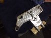
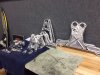
I finally got the suspension polished. The machining Fran does on these cars is amazing. Everyone that has come to the shop has commented on the billet suspension. Polishing just brings it out a little more. I attached a few photos to show the process. On the single piece shown, I polished just the left end. Hopefully the photo shows the difference. A pair of spiral sewn rag 6" rag wheels and "white" block polish really did the job. The more sewing on the side of the rag wheel the better, because you need the sewing to hold the wheel together with so much polishing needing to be done.
Attachments
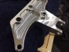
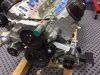
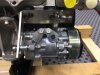
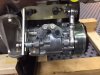
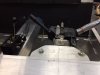
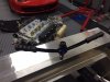
Having many things going at once, I also have been working on the accessory drives on the motor. I used RCR brackets for the compressor pump, adding the M10 x 1.5 bolts to mount the brackets and the M8 hardware to attach the compressor. I am working on finding a better turnbuckle to adjust the belt tension on the compressor. This has just two Heim ends screwed together, but it requires removing an end to adjust it. As for the alternator, Allan's help guided me. Unfortunately, I have an LS3 block with LS7 heads, and the bracket for mounting the top idler pulley needs to be an LS7 bracket, which is now on order. The LS7 heads have a lobe interfering with the top AC bracket mounting, so it needed a little visit to the grinding wheel to make it fit.
Attachments

I am having a shop make solid spacers to replace the washer stacks used to get things mounted.
Looks nice Mark. On the turnbuckle, why don't you use two female ends? One left hand thread, and one right hand thread. Then you can get a stud that has different handed ends. Then you could screw it together or apart without taking it apart. Just a thought.
Regards Brian
Regards Brian
Thanks for your suggestion. Looks like Amazon may save me some work. I found both left and right threaded M8 female Heim Joints, and found a turnbuckle bolt M8 x 57mm. We will see when the parts arrive, but it should work.
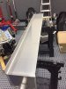
After packing up all of the suspension parts for anodizing and the brake calipers for powder coating, I started sound and heat barriers. The front foot well was first on the list. I drilled the holes I knew I would need for the master cylinder reservoirs and wiring, then made a template out of cardboard. I will be using Lava Shield on the outside and Damplifier in the cockpit foot well.
After packing up all of the suspension parts for anodizing and the brake calipers for powder coating, I started sound and heat barriers. The front foot well was first on the list. I drilled the holes I knew I would need for the master cylinder reservoirs and wiring, then made a template out of cardboard. I will be using Lava Shield on the outside and Damplifier in the cockpit foot well.
Attachments
Ken Roberts
Supporter
I am finally able to get started with the build. After taking inventory and putting the parts in storage, I wanted to build something, so I assembled with Tilton Pedals. As many have already said, they are nice! It is hard to know how to adjust them until they are in place, but at least I know how they can be adjusted.
Most of this build will be pretty standard, but I do have a few things that may be unusual. I want to get those started, so I don't use up space with standard things that may be needed by the few special items.
The air intake is one of the special items. I want cold air intakes using the side body scoops. I understand the Robertson race car has this feature.
The first order of business to achieve with was to decide on air cleaners. With help from contributors earlier in this build thread, I decided on K and N's cold air intake. I am aware that at high rpm levels, the air flow may be less than ideal, but is will be close.
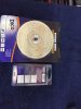
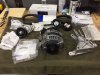
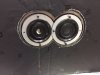
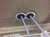
The first problem is that the 4 inch throttle body diameter down to the 2.75 inch air cleaner diameter requires an adapter that no one makes, not K&N, or anyone that I could find (see photo). Fortunately, the local Ace Hardware plumbing dept. had 4 inch to 3.25 inch adapter. I then found a an automotive piece that had an outside diameter of 3.25 and would go down to 2.75. First (of many in the future) problem solved.
Here is a source Mark for the required silicone hose couplers. They come in either blue or black and two different lengths 3" or 4".
HPS High Temp 2.75" > 4" ID x 3" Long 4-ply Reinforced Silicone Reducer Coupler Hose Black 70mm 102mm
Last edited:
Ken Roberts
Supporter
A better looking/performing idea would be to unbolt the flange sections of those K&N filters, cut the 2.75" flange off and weld on a 4" flange (if possible).
Ken: Thanks for the info. I will look that up. The K&N casing is a composite material, but there mat be a way to modify it. The air intake was the first think I approached in the build. Now that I am into it a little, I have greatly broadened my thinking and problem solving skills. I like the cold air intake aspect, ut the diameter may need to be larger leading to the throttle body. Any thoughts?
Ken Roberts
Supporter
You could possibly replace the composite flanged section with a copy made out of aluminum plate with a 4" flange welded to it. Personally I would relocate the filters away from the sides of the engine. They are blocking the view of those beautiful carbon fiber valve covers.
I would use 90 degree (large radius) elbows right after the throttle bodies and then go over the frame sections and then mount the K&N filter assemblies down lower in front of the rear tires. I would not use those filters as is though. They just look fugly with the necked down to 2.75" section. Additionally I think having that long section of corrugated tubing will hurt flow. I'll bet it was flow rated by K&N under ideal conditions. Your long sections of 4" hose to pick up cold air is far from ideal.
Unbolt the flange from the filter assembly and post a picture of the backside. If it looks simple enough you could mail me one of them and I'll reproduce them in aluminum with a 4" flange.
Congrats on your retirement Mark. I just retired this summer too.
Last edited:
I have the engine out of the car right now, working on the accessory drives and putting heat barrier on the firewall. when I get engine back in the car, I will revisit the air intake. You can see the goal, but my execution may need some more work. Thanks for your help.
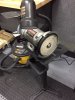
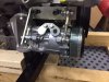
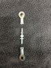
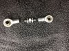
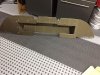
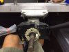
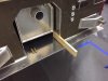
I have been working on a number of projects all at the same time, but wanted to wait on posting things until I could show some of the final results. The AC Compressor was previously attached, but I did not include a turnbuckle to adjust the belt tension. With advice from Forum members, I looked on the internet and found the parts that could become a turnbuckle. Heim Joints in both left and right threads, and a turnbuckle bolt from Summit Racing. The parts when assembled were too long, but a little time on the grinding wheel solved that. As you can see in the photos.
Attachments
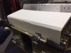
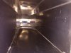
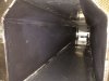
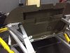
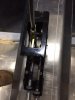
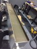
I have the Gas Tank out and am working on that. With the tank out, I want to keep the sound of the shifter kept to a minimum, so I an using Spectrum, from Second Skin Audio, to help with that. I applied three coats in the tunnel.
Attachments
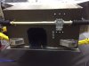
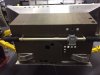
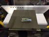
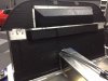
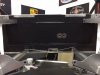
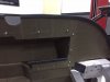
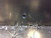
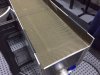
Sound Deadening the Firewall is next on the agenda. I used Damplifier Plus, from Second Skin Audio. Relatively light weight, as compared with some of the competition, and easy to use. I did the complete firewall, both engine side and interior side. The holes are for the shifter cables. I am looking for a detailed engine bay, so I used grommets and a trim ring.
Attachments
Mark - very fun to see your progress, happy to have another active build thread going. It'll be interesting to see how things differ between the SLC and GTR.
On the AC compressor mounting, not sure if it's a camera perspective thing or real, but is the turnbuckle in line or does it have an offset between the compressor and mounting position? It looks as though the turnbuckle wants to be right on top of the flange. If the turnbuckle is tilted it may allow the compressor to twist in its mount and place a moment on all the mounting tabs.
On the AC compressor mounting, not sure if it's a camera perspective thing or real, but is the turnbuckle in line or does it have an offset between the compressor and mounting position? It looks as though the turnbuckle wants to be right on top of the flange. If the turnbuckle is tilted it may allow the compressor to twist in its mount and place a moment on all the mounting tabs.
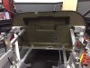
After the sound deadening, the heat barrier needed to go on. I used Lava Shield. Expensive, but I thought is was the best looking of the choices. It covered the Damplifier in the engine bay. I decided to put some trim along the edges to reduce fraying and to finish the look. Much of it will not be visible, but I could not decide where to start or stop, so I did it all.
Attachments
With the tank out of the tunnel, the shifter needs to be mounted. I learned from Dean the difficulties that can come from mounting the shifter after the tank went in. He did an amazing job of mounting the shifter, but I don't have his skill, so I wanted to get it done. In mocking up the interior to determine the position of the shifter, It was apparent that the steering wheel was not aligned with my desired seating position. The steering wheel was originally mounted in line with the line drawn on the mounting plate. I shifted it to the left as far as the mounting plate would allow. I will be using an interior "Tub" when it is finished, so I wanted to be able to leave some room between the seat and the tunnel. To make sue the shifter remains where I want it, I drilled three more holes in the shifter housing, for a total of seven holes that will screw into the 1/4" aluminum tunnel material.
Attachments
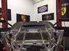
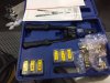
I will be following Dean's method of installing the fuel tank. I drilled the interior side of the tunnel and into the "Legs" of the fuel tank. The fuel tank on this car is a beautiful piece. There is a two inch by 8.5 inch space under the tank to run coolant tubes, battery cables, brake lines, AC lines and radiator vent lines. I used Rivnuts to attach the tank to the tunnel. The Rivnut tool was recommended by Dean and works great.
Attachments
Since the coolant tubes will be running under the tank, thermal insulation is needed to keep the heat given off by the tubes from heating the interior and the fuel. I used Lava Shield in this area. I plan to put additional heat barrier around the tubes. Again, using Dean's technique, I will use a piece of wood as a spacer to keep the screws from deforming the tank "legs."
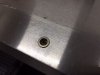
I had a problem with the tank not always fitting into the tunnel. There appeared to be two sources for this issue. The welds on the front edge of the tunnel, although amazing, had a few rough spots that were rubbing on the top of the tank. A little time with the Dremmel and that problem was solved. The legs to the tank were also needing to be trimmed. An abrasive wheel on an angle grinder to the bottom edges of the tank legs solved that.
I wanted to put some trim on the bottom edges on the tank legs to serve as a sound dampener.
Attachments
Hi Cam:
You are right. I will go back and add a spacer to get the turnbuckle aligned. Thanks
You are right. I will go back and add a spacer to get the turnbuckle aligned. Thanks
Similar threads
- Replies
- 3
- Views
- 2K
- Replies
- 9
- Views
- 809
- Replies
- 5
- Views
- 941
- Replies
- 63
- Views
- 6K