
- Forums
- GT40 Replica Manufacturers' Corner
- RCR Forum - RCR40/SLC/917/Superlite Aero
- The SLC Clubhouse
You are using an out of date browser. It may not display this or other websites correctly.
You should upgrade or use an alternative browser.
You should upgrade or use an alternative browser.
Mark's GT-R Build
- Thread starter mksetter
- Start date
Mark, good info. I am requesting a quote from Armor Tech. I used your name so that there would be no ambiguity.
Thanks again, Mike
Thanks again, Mike
Hi Mike:
You will not be disappointed with Armor Tech. Hope your build is going well.
You will not be disappointed with Armor Tech. Hope your build is going well.
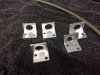
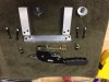
I started the brakes lines and needed some brackets to mount the junction between the solid lines and the braided flex lines. A little angle aluminum as a starting point, cut, drill, and finish. I worked on the front lines today and will start the back lines later, along with working on all of the stuff that needs to go in the tunnel.
Attachments

I know the dry lubricant will reduce any friction in the suspension, but it also looks great, with the matte gray finish. The photos show one connection not sprayed and another with the washers and bolt sprayed. I may go thru and spray up the nuts, etc. to get a consistent look.
Attachments
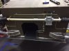
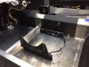
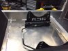
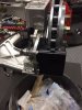
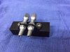
It seems I am working on many things at the same time, so this post is on the seat mounting. I removed the seat to show the mounting hardware. I want to have the ability to let others drive the car, so I am putting Sparco seat adjustment runners on the driver side. In addition, I plan to add Second Skin Luxury Liner Pro to the interior surfaces, including the floor, as well as carpeting. As a result, I needed to make a spacer out of one inch steel square material to get the seat runners and the seat above the liner and the carpeting. As the photos show, the Sparco runners are designed for seat support brackets that are closer together, so the handle joining the runners had to be sectioned and a solid aluminum rod put in the handle to extend the width. I plan to epoxy the rod in place and use heat shrink tubing over the entire handle area to hide the seam.
The photos also show that I mounted the adjustment handle to the rear. With the cross beam in the foot well, the seat adjustment handle ran into the cross beam when in the forward position.
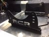
I painted the seat supports in a rough surface black to help hide the lettering in the support. One support bracket has the lettering in the correct orientation. The others have the lettering backwards. When the seats are mounted, the black hides the letters. I put the correct one on the left of the driver side since this is the bracket most visible. The passenger bracket ends up very close to the door sill, since the passenger side is much narrower than the driver side. Obviously the console hides the inboard lettering.
The photos also show that I mounted the adjustment handle to the rear. With the cross beam in the foot well, the seat adjustment handle ran into the cross beam when in the forward position.
I painted the seat supports in a rough surface black to help hide the lettering in the support. One support bracket has the lettering in the correct orientation. The others have the lettering backwards. When the seats are mounted, the black hides the letters. I put the correct one on the left of the driver side since this is the bracket most visible. The passenger bracket ends up very close to the door sill, since the passenger side is much narrower than the driver side. Obviously the console hides the inboard lettering.
Attachments
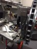
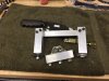
Another project for the day was to mount the Parking Brake Calipers. Like so many things about this car, these are quality items. In one of Allen's videos, he goes over this process. I am a novice, so reading the build logs has really helped me proceed with some confidence. Allen suggested mounting the bracket at the "corner" in the spindle, but in my situation it needed to be about 3/4 of an inch below that corner to get the most caliper contact. I had to use a few washers as spacers between the bracket and the caliper to get the bracket into the "meat" of the spindle aligned with the edge of the spindle, as Allen suggests. Thankfully, I have a great hardware store a mile from my shop, so my daily trips to get the bolts, etc. needed for the day's project is really easy.
I am waiting on some 1.5 inch solid aluminum stock to make the bracket for mounting the Parking Brake Handle. I plan to put it left of the driver seat, drilling through the base of the firewall to run the cables along the frame rail.
I am waiting on some 1.5 inch solid aluminum stock to make the bracket for mounting the Parking Brake Handle. I plan to put it left of the driver seat, drilling through the base of the firewall to run the cables along the frame rail.
Attachments
Mark
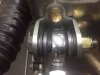
Just a thought. I looked at how your braided line runs to the banjo on the Brembo. I ran my the same way and noted that during steering the braided line acts as a lever on the brembo banjo since there is no key to hold the banjo in place. My fear was that lever force could cause some movement in the banjo and create a leak or even brake failure. Now I agree many have never had a problem, just me over thinking the issue
I changed the orientation of my line to the banjo, the movement of the line to banjo is a forward/aft movement with no chance of a sideways force.
Again just a thought, crazy as it sounds.
Thanks for sharing your thoughts. Do you have a photo that shows this, by chance. Sounds like the right idea.
Mark
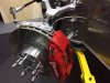
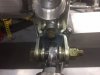
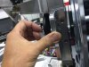
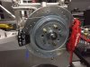
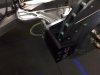
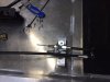
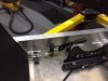
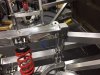
Note in the picture that I reoriented the approach to the caliper. Rather than come in from the rear with the braided line, I came in from the front of the shock tower so I could parallel the rotor. I used a P clamp (hidden in the picture) to secure the brake line to the suspension. I shortened the banjo and bought a slightly longer braided line. I have no issue with full range of movement or hitting the wheel barrel.
A perpendicular approach without a keyed banjo simply gave me pause.
Attachments
Both great suggestions! Thanks, Dan, for the photo. I can picture exactly the issue now. And changing the bolt heads is an easy fix now, making the alignment easier later.
Again, being a novice at this, I really appreciate your suggestions.
Again, being a novice at this, I really appreciate your suggestions.
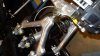
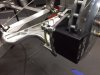
After mounting the parking brake calipers, I worked on running the cables. I struggled with the cable springs, then finally asked for help on the RCR forum and Ken confirmed my suspicion of needing to alter the length of the cable springs. Thanks Ken. A little time shortening the springs and the caliper end of the cables worked great. Now for mounting the brake handle.
Attachments
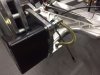
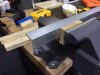
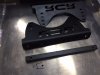
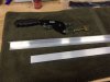
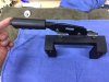
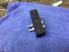
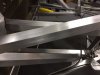
With no fabrication experience, but having some square solid aluminum and some angle stock, I made a bracket for mounting the hand brake. I plan to add Second Skin Damplifier Pro, Second Skin Luxury Liner Pro, the fiberglass tub and carpeting, so I made the brake handle four inches off the floor pan. After running the cable through the firewall, I also made the mounting for the cables.
Attachments
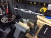
With the interior mocked up for the steering wheel, seat position and shifter position, I positioned the hand brake, painted up all of the parts and put it all together. Knowing the interior tub will require around .5 inches, everything is mounted with that in mind. Tested it out. Works great!
Some might wonder why work on the interior at this point, but my thinking is that I want to get all of the layout finished while I have the roll bar out. The interior tub requires the roll bar be out to install the tub. I also want to Damplifier Pro on the floor, but hate to drill thru it because it really plugs up the drill bits. With all of the holes in the floor completed, I can put in the sound deadener and the tub, with minimal issues (hopefully).
Some might wonder why work on the interior at this point, but my thinking is that I want to get all of the layout finished while I have the roll bar out. The interior tub requires the roll bar be out to install the tub. I also want to Damplifier Pro on the floor, but hate to drill thru it because it really plugs up the drill bits. With all of the holes in the floor completed, I can put in the sound deadener and the tub, with minimal issues (hopefully).
Attachments
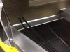
I wanted to clean up the frame rails before adding more to that area. After reading all of the comments on this subject, I decided to use fine steel wool and wipe on metal preservative. Easy and looks great.
I now need to attack the items that need to go in the tunnel. Also working on the front of the motor. I think I have the water pump issue solved with the help of my friends at Mannix Automotive next door. I am taking a break over the Holidays heading to Philly, but will be back after Christmas.
Building this has been a ton of fun!
Attachments
Build is coming along nicely, some really clean work! If you have the time check out the Simeone museum while in Philly, some great GT40 inspiration there. And if you're ever a little north of the city and want to compare GT-R notes my garage is always open.
I did not think of using Damplifier on the inner tub. Thanks. I suspect that the tub may well be resting on the Luxury Liner Pro given the thickness of the Damplifier Pro and the Luxury Liner Pro, but we have yet to see the interior tub. I saw a photo of the CAD/CAM of the mold. Looks great!
Similar threads
- Replies
- 3
- Views
- 2K
- Replies
- 9
- Views
- 809
- Replies
- 5
- Views
- 941
- Replies
- 63
- Views
- 6K