Mason’s Build: Superlite SLC

Ron McCall

Supporter
Speaking of rims, the C6 Base corvette rims do NOT fit the SLC, there is not enough offset for the calipers. These were provided by the seller, so I assumed that they belonged with the kit, but apparently they do not.

Now it's time to go shopping for some wheels!

What type of use will the car see? Street car? track car?
I have a set of CCW s that I would like to sell. One front wheel is cracked but the other three are nice.

Ron
 

Howard Jones

Supporter
If you use corvette "standard" width rears instead of ZO6 rears then you will need spacers. I may have some out in the shop. I'll look and take a picture. However if you go looking for wheels I would strongly advise a ZO6 set.
 
Last edited:
Hello Ron, I may be interested in the CCWs, the car will see 80% Street/Car Show duty and 20% HPDE / Track Days (No Slicks).

Howard, thanks for the insight, I'm only considering wheels that come in C6 Z06 fitment. Let me know what you got, since I may want to have some "knock around" wheels while I'm building her up for the next 18-24 months.
 

Howard Jones

Supporter
Mason, I don't have any for sale as I am using them for track tires. However check ebay for "ZO6 corvette wheels and tires" every couple of days. You'll find something you can use pretty quickly.
 
Hello Ron, I may be interested in the CCWs, the car will see 80% Street/Car Show duty and 20% HPDE / Track Days (No Slicks).

Howard, thanks for the insight, I'm only considering wheels that come in C6 Z06 fitment. Let me know what you got, since I may want to have some "knock around" wheels while I'm building her up for the next 18-24 months.

I have a set of rollarounds for sale if you are interested. PM me for details.
 
HELP! Does anyone know the dimensions of the stock SLC fuel tank? I need this information to make sure the engine does not interfere with the fuel tank and it's fittings.

I ended up buying the "Z06 wheels from Paul Teutul Sr" that were on eBay, thanks Howard Jones for the link! I will go pick them up from Oregon this weekend. One step closer to a rolling chassis!

A buddy came over to check out the project and he helped me roughly place the car together. It was cool to see it with the body laid in place and a good opportunity to sit in the driver spot and make vroom vroom sounds. LOL

IMG_3069.JPEG


The previous owner had hard anodized the suspension and consequently some of the bolts no longer fit in the holes, so they had to be reamed out with a straight flute reamer.

IMG_3039.JPEG


My wife also got in to confirm pedal placement.... or to make engine noises and row the wheel back and forth a bit.

IMG_3042.JPEG


Finally was able to piece together all of the suspension and remove the full race cage (For Sale if anyone is interested!).

IMG_3082.JPEG


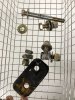
A shot of the rear suspension, note that there has been no consideration for Caster/Camber/Toe settings just yet. I plan on taking the whole thing apart to lube the rod ends adjust all of the lengths and then do a loc-tite re-assembly of each corner.

IMG_3084.JPEG


The beautifully built race cage (PM me if you are interested!)

IMG_3086.JPEG


I removed the welded in Fuel cell cover, because I'm converting to a standard Fuel Tank. I have the FIA certified fuel bladder which expired in 2017 if anyone is interested in it. I didn't want to deal with taking the car apart every 5 years to replace the fuel bladder.

Does the normal SLC kit come with a Fuel Tank Cover?

IMG_3092.JPEG
 

Attachments

  • IMG_3038.JPEG
    IMG_3038.JPEG
    245.9 KB · Views: 211
My goals are the following to keep the project moving forward:
1. Get it rolling and steering
2. Cut and modify the Chassis Bridge to fit the SLC V10
3. Weld coolant pipes
4. Run brake lines and plumb the braking system (I have hard lines, but no other parts, need to figure out all the flex line lengths/fittings and valves)
I didn't see much detail in the build manual about all of the brake hydraulic system elements and where to place them.

I also continue 3D scanning many of the SLC parts to help with planning my V10 install and custom Roll Cage.
This image shows my fresh scan of the Body Spider, Chassis, and Full Engine with Intake

EngineFitting.JPG
 
The car is going to be a bit twitchy with those rear toe settings :p Where is the pic of the cell? Can you adapt the aluminum cell into an actual gas tank? That cover is about the shape of the actual tank that Howard and I have in our cars. Mine being the full width of the chassis with internal surge and pump cell built in. The factory cover is a flat sheet that follows the 45 degree angle of the chassis (it does not bend to a flat vertical 'shelf' space as your cover does).

Nice emblem on the hood. (chuckle)
 
Mesa and Roger, thanks so much!!

Mesa, I will post some pictures of the Fuel Bladder, hopefully this weekend. The Top and bottom cover could be fashioned into some sort of fuel tank, but I don't trust my current welding skills for that project. I just got a quote from RCR for a tank for $495, which is probably less than getting a local fab person to custom build one for me.

Roger, thanks for the dimensions, I'm having some heartburn over jamming this fat engine into this chassis. I discovered that the RCR V10 modifications to the chassis included moving the bottom 2x2 beam 2" toward the front of the car AND a bridge to allow the V10 to fit.

BUT, once the customer (Dani G) mounted the engine in the modded chassis he ended up shifting the engine towards the BACK of the car.


Lower 2x2 Cross member Shifted Forward (RCR Factory Mod for V10)
1574402008033.png


Dani didn't have clearance for exhaust so he shifted the motor 2" Rearward. So, perhaps I do not need to shift the lower cross member for my build.
1574402134250.png
 

Neil

Supporter
If the engine moves forward more than 1" in a frontal crash, you will be bathed in fuel!
 
What is a safe non fuel bathing clearance for engine and fuel tank?
In mid engine configuration all engines could hit the fuel tank with a hard enough hit.
Perhaps a titanium brace could protect the tank? Thoughts?
 
A fuel cell is th safest way but does require some effort. Alternatively, have the tank pocketed to allow a crumple zone of sorts around the front offending parts on the engine. Use an electric remotely mounted waterpump!
 

Howard Jones

Supporter
Mason go to my build log and start at post #170. Lots of modification stuff on the OEM fuel tank there. Then right after that at post # 196 is what I did for the lack of firewall. Other than the cutout for the water pump pulley ( I have since changed over to a electric pump) I would still do all of that on any SLC I built.
 

Neil

Supporter
A fuel cell is th safest way but does require some effort. Alternatively, have the tank pocketed to allow a crumple zone of sorts around the front offending parts on the engine. Use an electric remotely mounted waterpump!

Good suggestions. A true bladder-type fuel cell will help considerably, too. Check with ATL or Fuel Safe.
 
Thanks for all of the suggestions, I do have a racing fuel cell bladder that is expired and I do NOT have an OEM fuel tank from RCR. I will study some other builds as suggested and perhaps fab my own fuel tank.
@Mesa Why the remote electric water pump? Is that for ease of maintenance?
 

Howard Jones

Supporter
1. Mechanical pumps are subject to engine speed. The RPM range of most V8s will exceed the efficiency range of water pump impellers. When the impeller is run at speeds above its range in will cavitate and really cause a lot of problems including failure of the pump itself, induction of air into the water, loss of system pressure, and reduction of cooling efficiency. Running it too slow reduces flow rates. You are forced to choose either too slow or too fast with pully selection.

Running a electric pump at the rpm that most favors it's efficiency range is a much better solution. Then the pump duty cycle can be varied to modulate flow rates and at the same time maintain coolant temp.

2. The MP must be located in a location that does not provide a tall enough water column (head) because it is high in the car on the front of the motor. In fact far more than 50% of the water in the system is below the pump inlet a mid engine layout. An EP can be located as low as desired in the chassis and allow for a much improved pump input pressure. Most of the coolant can be higher than the pump in the system, nearly all if done correctly. This is one of the most important factors in water pump design. Think dam and hydroelectric plant location in relation to the lake water level.

3. Packaging is easier to account for. Engine placement can be a few inches farther forward if desired and the pump can be placed low along side the motor instead on the front of it. Center of gravity can be better planned for in such a engine location.

4. EP's have improved to the point that they are warranted for 1000s of hours and can be repaired with replacement motors or impellers at a reduced cost to the original full pump cost. Frankly they are much easier to remove and replace than a MP in addition.

5. Custom fabrication is reduced and easier in my opinion. It's just a matter of locating the pump in the coolant line in the proper place. The front of the engine pieces can be purchased complete and would not need to be custom modified as in the LS system inlet tubing.

So that's my opinion for what it's worth (free). If you want to do this, then do it from the beginning and plan accordingly.
 
Last edited:
Back
Top