McLaren replica build base on a Manta

Terry Oxandale

Skinny Man
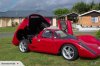
Had a good day today. Picked up a gutted LS block (free as long as I return it when finished) to mock-up some mounts, and best of all, received my wheels from Image Friday, and had the tires mounted this morning. So, even though nothing was really gained at this point, I cut the umbilical cord (rotisserie axles on the front and back), and set the car down on its own wheels for the first time since the build began.

standard.jpg


standard.jpg


standard.jpg


standard.jpg


standard.jpg
 
Last edited:

Randy V

Moderator-Admin
Staff member
Admin
Lifetime Supporter
Wonderful job!!!! You'll certainly have an original there!
Nice execution of some pretty good engineering principles!!!

:thumbsup:
 

Terry Oxandale

Skinny Man
Dry sump mock-up

I weighed member comments, looked around, thought about it awhile, and decided to go ahead and do the dry sump thing. I think once I get it all plumbed and fabricated it will definitely be the appropriate choice considering the 930 inverted engine positioning (thanks all for all the advice).

The below photos show a mock-up of the engine mounting with the dry sump pump in place. The motor mounts were going to be the biggest immediate concern. The OEM LSx motor mounts were going to be positioned in the same location as the oil pump (Dailey Engineering set-up). So I took the Corvette aluminum mounts, swapped sides, and then inverted them so that they now go out and down, instead of down and out. I’m guess from looking at the mount that it was originally designed for compression forces, and the new orientation places tension forces on it instead, but it’s a pretty beefy part, so well see if it holds up.

standard.jpg


standard.jpg


standard.jpg
 
Hi to everyone. I am new to this forum.
Nice to see that you guys keep these older gassers where they should be,
still running on the road or track :heart:.
Thought I would add some interesting pic's for you from trademe.co.nz

This is from a site in New Zealand much like your ebay.
A lot of real gems can be found here in kiwiland. :thumbsup:.
Cheers Dave
 

Attachments

  • 89508416_full.jpg
    89508416_full.jpg
    47.5 KB · Views: 613

Terry Oxandale

Skinny Man
More Progress

More progress during the last couple of weeks. First, figuring how to mount a Holley style LP pump without using their hermaphrodite U-bent mounting hardware. So I took off the bottom plate just to see what lurked inside and found that a rubber gasket and a thrust plate was it. This was just what I was hoping for because I wanted to mount the fuel pump via the base-plate instead of the bracket. So I fabbed up a new base-plate out of aluminum angle to replace the 1/8" steel plate from the manufacturer, and will be using the new base as a mounting bracket down low and away from any engine heat.

Fuel pump as it came out of the box. Note the thin plate at the base, and the horrid mounting bracket around the motor:
standard.jpg


The new bracket/base plate attached:
standard.jpg


standard.jpg
 
Last edited:

Terry Oxandale

Skinny Man
More Progress

Oh, but I'm not done yet. The oiling system was part of the work this week as well. I fabbed up a dry-sump tank to fit into one of the side pods, installed oil coolers at their appropriate locations (still need outboard supports), and a remote filter arrangement.

standard.jpg


standard.jpg


The dry-sump system that I'm using:
standard.jpg
 

Terry Oxandale

Skinny Man
More Progress

Stay with me, I'm still not done yet. The last thing I did was fab up a shifter bracket for the shift-rod. At first I wanted to do the usual rifle-bolt set-up, but it bothered me that it twists the rod off-axis (from most examples I've seen) which makes the rod move laterally. So what I did was dismantle an old U-joint, drill and weld new tabs to extend the arms far enough out to allow the acute angles, thus allowing it to twist the rod on-axis. I was curious to see how effective this was at twisting the rod and found I could still twist the rod easily even up to 80º of angle (but obviously I'd not be able to pull the rod in or out of the case at that point). The final operating angle will be somewhere around 30º. If this works out well, I'll take a good new U-joint and do the same thing, except include the bearings and cups.

standard.jpg


standard.jpg
 
Last edited:

Terry Oxandale

Skinny Man
More progess

Oh, and least I forget, the starter. This just about got the best of me. After finding out a "normal" starter had interfered exactly where the lower frame rail resided (no, it couldn't be just above it, or just below it, or even extended away from it, but instead, in the exact same space and time). Adding insult to injury, the pick-up point for the lower arms was at this exact location as well.
So I tried a clockable starter only to find out that the adjustment range did not provide any relief! So after figuring out exactly where a pair of new clocking holes needed to be drilled, it became painfully apparent that the motor's reduction gearbox would lie directly over the mounting tab hole on the clockable mounting plate (jeez!). Fortunately, this exact location of the gearbox happened to have a void just here a bolt would need to penetrate the casing (exactly between stafts and gears). So I carefully drilled everything out, helicoiled the mounting tab and the gearbox case as a unit after the single mounting hole was drilled, and stuck it on the car. My only concern at this point is the paper thin clearance between the starter motor and the CV joint above it. UGGG!

Here's a photo of the finished starter with the gear reduction box right behind the normally clear and open hole used to mount the starter onto the bellhousing:

standard.jpg
 
Terry,
I like it. I suppose you could curve the two blades coming into the universal from the shift rod to add your 30 deg. I may do the same setup with shift rod too. I would have to do the breach system, the shift rod is on the side of my Audi box. I like your welding too nice job on the tank.
Dave
 
you, my friend, are not playing around.

Dailey engineering stuff is beautiful. If I ever blow my LS7 due to oiling issues, that's what I'm getting!

Amazing evolution of the original kit you bought.
 
Ox you are doing some really nice fab work, wish I had the equipment (not to mention the skills) to do such work. Placing all the coolers and rads in a logical location (where the ducting is) is one of the things that separate a "kit" car from a "hand crafted car". You are doing the old girl serious justice, i don't think I've seen a better chassis on one of these Mantas before.

You might want to check out Howard Jones' shifter bracket setup on his SLC/Porsche, nicely thought out although I believe it's cable operated if that's an option for you.
 

Terry Oxandale

Skinny Man
...wish I had the equipment (not to mention the skills) to do such work..."

In all honesty, the fabrictation is all done with a Harbor Freight drill press, a Sawzall, and a lot of files and elbow grease (oh, and a welder comes in handy)

It's amazing what you can do with minimal tools. I can't imagine what I could do with a milling machine, a metal lathe, and other things I don't have room for.

ox
 
Aww, come on Ox, you can never have enough tools! Or enough SPACE to put them in..
 
Last edited:

Terry Oxandale

Skinny Man
So true. Sometimes I think I spend more energy in the garage figuring how to rearrange stuff just so I can get another shelf or something put into the garage. Heck, I've got to rethink the floor plan just to move the trashcan within the garage.

ox
 
Terry,
I have the lathe but your welder makes mine look like a toy. You must have one of the older transformer types. Did you make it yourself? I may mount my tubing bender in the basement so I can do more work. Roll hoop control arms etc. Did you figure the starter out yet? Most guys just cut out a section and shape a piece of steel and tack it in place to get clearance.
Dave
 
Back
Top