Modern-day Miura

Gas/Brake Pedals Installed

In parallel with wiring installation, the brake system is also being installed. For that, I decided to start with the pedals and work outward to the disk brake calipers. Given the somewhat horizontal seating arrangement in the Miura, it seemed like a good idea to build some adjustability into the pedal locations for drivers with different leg lengths. The pedals are floor mounted using a Wilwood integrated pedal and master cylinder setup. By mounting the pedal set onto a ¼” aluminum plate and then drilling a series of adjustment holes into the plate, I was able to achieve 3” inches of front to back travel for the pedals. The chassis floor is also ¼” aluminum plate so the combined ½” of plate gives the pedals a rigid mounting.

uiUPRKv.jpg


To keep pedal adjustments as simple as unscrewing four nuts, move pedals, and re-installing the nuts; the throttle cable mount also needed to be anchored to the same mounting plate. After digging through my scrap aluminum bin, I came up with this arrangement. Given the engine placement behind the gas pedal, it’s a straight pull between the pedal and cable to open the throttle plates.

U4nBf9V.jpg


Y1RxmB8.jpg


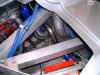
Having master cylinders whose location can move adds a wrinkle into the plumbing. Namely, flexible lines are required prior to the rigid tubing. Here’s what I came up with.

OaQk1rq.jpg


The last piece for this part of the brake system was mounting the fluid reservoirs. My preference for simplicity of checking and re-filling the reservoirs was to mount them on the front side of the front bulkhead. But after fitting a tire into the spare tire well, there just wasn’t enough room left over for the three reservoirs. So the next best location was the backside of the front bulkhead and I’ll need to build in an access door when this area is closed off with sheet metal.

0QFiEpD.jpg


So far the most challenging part of the brake system has been figuring out the multitude of fittings, hoses, and tubing that is required. 3/16” tubing for brakes, ¼” tubing for clutch, adapting between NPT and AN threads, angled fittings, bulkheads, and the need for residual pressure valves because the master cylinders are below the calipers makes for a mind boggling quantity of parts that need to be sourced and procured.
 
May be too late to say it, but if you have the reservoirs higher than the wheel cylinders (calipers) you don't need the residual valves. The head from the reservoirs gives the head pressure to keep the calipers from bleeding back.
 

Randy V

Moderator-Admin
Staff member
Admin
Lifetime Supporter
May be too late to say it, but if you have the reservoirs higher than the wheel cylinders (calipers) you don't need the residual valves. The head from the reservoirs gives the head pressure to keep the calipers from bleeding back.
I have installed them a number of times, not so much to control gravity drainback, but to keep the brake pedal high When your master cylinder volume is less than what is generally required for the volume of the calipers / wheel cylinders. They’ll be just fine.
 

Ian Anderson

Lifetime Supporter
Hi Pedal set up links interesting.
had you considered some car seat runners to mount it on?
saves having to spanner it to change the pedals.

Of course powered runners means not even having to dive into the footwell

Ian
 
Hi Pedal set up links interesting.
had you considered some car seat runners to mount it on?
saves having to spanner it to change the pedals.

Of course powered runners means not even having to dive into the footwell

Ian

I did think about using car seat runners but didn't go that way as it would have raised the pedals even higher. The seat adjusters I have are 1" high so it would be a 1 1/4" pedal lift. Given the low roofline on the Miura, I'm using a drivers seat whose seat bottom is only 3 1/4" above the chassis floor (even with the seat adjusters on it) so the top of my head won't hit the roof. I'm trying to avoid the feeling of reaching up for the sweet spot on the pedals. The other consideration is I think pedal adjustments will be in-frequent so the 10 minutes or so that it will take won't be a big deal. Getting down into the footwell would certainly be a pain though. Oh yeah, given an access door is needed for master cylinder reservoir access, I'll just need to make sure the door is large enough to access the pedal fasteners as well. No need to stand on my head for pedal adjustments that way.

On the other hand, if after driving the car some and if the pedals feel low, I can easily swap in a set of seat adjusters because everything else needed for pedal adjustment is already in place :)
 
Actualy, the man in the pic is Rod Stewart itself in front of his house, apearently he owned two Miura's

I guess long hair and a fur coat are poor gender identifiers for 70/80's era pop stars? This is suppose to be one of the Rod Stewart cars recently sold at auction.

4863 Rod Stewart car 5.jpg


Must have gone through a color change sometime in the ownership history. While I don't usually like blue on a Miura, this color blue certainly shows off the body lines nicely, much more than the lighter colors from earlier photos.
 
Glad to see progress on the Miura!
On the topic of Lamborghini, a couple in our local driving club recently bought one of Rod's cars

Screenshot_20220730-124331_Facebook.jpg
 
Brake Lines Completed

Progressing on with the brake system, the brake hard lines and hoses are now in place. It took a bit of head scratching to figure out chassis mounts for the front brake hoses. I ended up using billet hose/tube separators along with -3AN bulkhead fittings for the mounts.

c9a23ja.jpg


The chassis mounts for the rear brake hoses were much easier; short pieces of aluminum angle did the trick. It’s much easier to figure out the hose mount locations for the rear where you only need to account for vertical motion. For the front, you need to account for the combination of vertical motion and the caliper pivot as the wheels change angle.

D9NaLeL.jpg
 
Coolant Lines Completed

The coolant lines on this Miura chassis run up the center of the chassis under the gas tank. While this routing is probably ideal for a longitudinal mounted engine, with a transverse engine it makes for some challenging coolant line routing right by the engine front side exhaust header. A key consideration for the coolant system was to make sure the coolant fill port is the highest point in the system. In addition, the Coyote engine has new style coolant hose fittings which needed to be converted to good old hose and clamp style fittings.

IWGl9iD.jpg


Starting at the engine coolant outflow point, I fabricated a coolant fill tank that hopefully will also help degas the coolant. This tank was welded onto the coolant neck on the top of the engine along with a bung for mounting the coolant temperature sensor. This way the electric water pump controller will get a reading at a point where the coolant will be its hottest. A 1 ½ ” tube exits the bottom of the fill tank, runs down in front of the cylinder head to the front side of the engine. The thermostat housing was eliminated with this coolant fill tank as it was no longer needed.

vS54rnV.jpg


This is looking upward by the engine front side header from below. I welded up some aluminum mandrel bends to snake around the oil filter, maximize spacing away from the header and connect up with the tubes going to/from the radiator. Hidden behind one of the A/C hoses is the heater hose that also goes up the chassis center. The next time I have the engine out, I’ll fabricate some heat shielding to help protect the silicone and rubber hoses.

wBVH9QQ.jpg


The coolant return line from the radiator connects up to a fitting that replaces the mechanical water pump.

wqBqQmI.jpg


An electric water pump is located at the radiator outflow port.

n3aV2Li.jpg


A small auxiliary pump is used to push hot coolant up to the heater core in the passenger side footbox. It was a challenge but the hose feeding this pump is just below the level of the coolant fill cap. I’m guessing it will likely take some trial and error to figure out how to get all the air purged out of the coolant system. I might need to add a bleeder value in that hose but I won’t go there until I get some evidence that it’s needed.

Oh well, I’m hoping for the best that this coolant system will keep the engine temperatures where they should be and the cockpit warm and toasty when it’s cold outside. Only time will tell…
 

Howard Jones

Supporter
Those Davis Craig pumps like to be mounted so that the input port (center) is vertical so that any air trapped in it will naturally want to flow up and out. Note the main feed to the header tank on top of the input tubing. It will also prime more efficiently because the impeller/pump area remains in a submerged position. Go ahead and leave it as is for now but if you run into an issue, well you know what it is.

I looked at your pic again and I'm not really sure of the picture orientation. If it's looking down into the chassis then I think it would benefit from being flipped over as I alluded to above.
 

Attachments

  • HPIM2332.JPG
    HPIM2332.JPG
    66.6 KB · Views: 117
Last edited:
Those Davis Craig pumps like to be mounted so that the input port (center) is vertical so that any air trapped in it will naturally want to flow up and out. Note the main feed to the header tank on top of the input tubing. It will also prime more efficiently because the impeller/pump area remains in a submerged position. Go ahead and leave it as is for now but if you run into an issue, well you know what it is.

I looked at your pic again and I'm not really sure of the picture orientation. If it's looking down into the chassis then I think it would benefit from being flipped over as I alluded to above.

I think you're probably right Howard. This is my first time building up a "non-traditional" cooling system and I'm guessing there's some things that are currently not optimal. I've elected to use "keep it simple" as a first guiding principle, plan to thoroughly test, and then modify the implementation as needed. The current pump placement and orientation resulted from trying to keep the pipe routing and connections as simple as possible.

I'm almost to the point where enough of the basics (i.e. wiring, coolant and fuel plumbing, brakes, exhaust, etc.) will be in place to test fire the engine and start the shake out process with the chassis as a "go-kart". The major piece I'm missing right now is the wheels and I'm am working on them.

I'm at a bit of a quandary as whether to have the exhaust ceramic coated prior to test firing the engine or sometime later prior to final assembly. My gut feeling is to do it now while the headers and head pipes are still clean inside (they were rubbed down inside with alcohol prior to welding). I think the ceramic coating will need to be outside and inside to minimize radiant heat loss. I'm worried that firing the engine and running it around the neighborhood roads will result in enough soot inside that coating inside might be an issue. Has anyone had a similar situation? Any guidance from first hand experience is very welcome on this topic.
 

Neil

Supporter
I think you're probably right Howard. This is my first time building up a "non-traditional" cooling system and I'm guessing there's some things that are currently not optimal. I've elected to use "keep it simple" as a first guiding principle, plan to thoroughly test, and then modify the implementation as needed. The current pump placement and orientation resulted from trying to keep the pipe routing and connections as simple as possible.

I'm almost to the point where enough of the basics (i.e. wiring, coolant and fuel plumbing, brakes, exhaust, etc.) will be in place to test fire the engine and start the shake out process with the chassis as a "go-kart". The major piece I'm missing right now is the wheels and I'm am working on them.

I'm at a bit of a quandary as whether to have the exhaust ceramic coated prior to test firing the engine or sometime later prior to final assembly. My gut feeling is to do it now while the headers and head pipes are still clean inside (they were rubbed down inside with alcohol prior to welding). I think the ceramic coating will need to be outside and inside to minimize radiant heat loss. I'm worried that firing the engine and running it around the neighborhood roads will result in enough soot inside that coating inside might be an issue. Has anyone had a similar situation? Any guidance from first hand experience is very welcome on this topic.
I had my long-tube headers CeraKoated and they are holding up very well, even though I've driven on a salt surface.
 

Howard Jones

Supporter
If I remember correctly when I had the headers on my GT40 ceramic coated they wanted to know if they had been run yet or freshly built when I called them prior to shipping them off. I think the guy was saying if they were used and cleaning the inside became an added cost to them then they were going to pass it on to me. I don't really remember all the details of that because it was something like 20 + years ago. I would simply call them and ask. I do know they clean them inside and out prior to the coating as part of the procedure so maybe it doesn't matter very much. I think it was more a thing about just how used they were as in rust and caked-on carbon being a problem.

As Niel has, I recommend coating them inside and out. Mine are 20+ years old and they have never rusted, They don't look new anymore but I would say they still look very good. Not quite excellent but very good still.
 
Last edited:
It’s a Roller!!

It’s been quite a while since the Miura project has had progress worth an update. A few months ago, I commissioned the making of some custom rims to mimic the look of the original Miura Campagnolo rims. Over the last few years, I had searched extensively for aftermarket 17” rims that had the “Miura look” and came up empty. I thought about using pin drive wheels commonly used on Cobras and GT40s just couldn’t warm up to that choice.

Then someone told me about Augment Wheel that custom makes rims at a reasonable cost (for custom rims that is :) ). Dan at Augment was able to capture the Miura rim look in a CAD design including some faux knock-offs with lug nut covers. Here are the rims that resulted.

Td6rt7V.jpg


tRB07gp.jpg


As compared to an original rim. The main difference in look is the proportion of rim to tire sidewall height. I want to use modern performance tires so short sidewalls it is.

TReu6Zn.jpg


With the new rims and tires, the Miura chassis now can be rolled out of the garage to get a view from more than a few feet back.

opkkibZ.jpg


l8bZqBr.jpg


vhttx3p.jpg


Hopefully I’ll have the car moved to the new workshop soon and start making regular progress on it again.
 
Sheetmetal for dash gauge mounts

I’m finally making some progress on the Miura project so it’s time for an update. The new garage/workshop is now sufficiently complete to let the fabrication work resume.

The Miura dash has the speedometer and tachometer mounted behind the steering wheel and all the other gauges mounted as two rows of three traditional round gauges in the center of the dash.

4863 Rod Stewart car 4.jpg


The factory used a molded plastic piece to hold the gauges. In a Miura upholstered in leather, this plastic piece always looked out of place to me. Functional for making the gauges visible but not up to par with the other dash fit and finish.

IMG_4162_a.jpg


I decided to make this panel from aluminum so it could be finished in wrinkle powder coat in an effort to improve on the original. I don’t have ready access to an original panel and so I’m recreating it from the pictures I have gathered. To figure out what angles and shapes are needed for the gauge recesses, I did a few iterations of cardboard mockups.

P1170553.JPG


This mockup looked about right and gave me the ability to make templates for the cut outs and gauge surround pieces. Each cut out is directly adjacent to its neighbor so I decided to do one at a time to leave enough aluminum in place to minimize the risk of burn through during welding. It took the first couple of insets for me to work out a good “recipe” for bending, shaping and welding to form a good looking gauge inset.

The first step is to make a cut out in the .063 thick base piece, bend the middle part at the desired angle and then cut out a .050 thick piece for the surround. I elected to use thinner aluminum for the surround to make it easier to bend and shape. Some metal shrinking was required to get a good surround fit up by the top of the gauge. I did the shrinks over a football post dolly given the small size of the work piece.

P1170529.JPG


P1170530.JPG


P1170531.JPG


After lots of welding, grinding, and cleanup; the raw metal piece came out nice. The flat aluminum base piece moved/warped quite badly around the edges during welding. This required some careful flattening to remove warp without cracking the welds. Truth be told, I did crack a couple of welds and had to re-weld and re-flatten.

P1170560.JPG


P1170554.JPG


I elected to punch holes for the gauges as the last step. I was afraid having only ¼” wide of aluminum next to the weld joint might result in melted scrap. I had to order a 2 1/16” hole punch die set to make the holes. I’ll post up another update once that arrives.

It’s clear to me now why the Lamborghini factory elected to make this panel from a mold instead of fabricating it. I’ll have a good several days work into making this one panel.
 
Back
Top