Norfolk Tornado

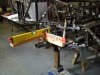
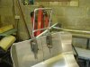
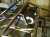
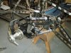
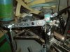
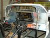
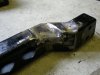
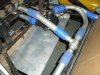
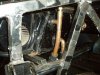
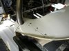
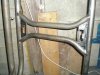
The roll cage is now fully welded in and dash cut to fit around front legs (thanks Tom for the idea of a very tidy design). The two plates on the roof bars are to take a couple of interior lights. The wiring for these will run through the roll cage, so a slave wire has been left in place so that the harness can be pulled through.

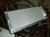
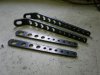
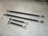
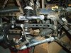
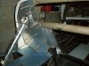
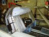
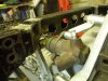
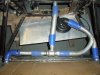
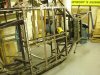
Seat straps are also finished. As there’s very little strength in the centre tunnel structure the additional cross-braces under the centre tunnel, now result in the seat straps effectively are now continuous from one sill to the other.

Regards
Andy
 

Attachments

  • P2080940.jpg
    P2080940.jpg
    36.4 KB · Views: 1,462
  • P2080941.jpg
    P2080941.jpg
    24.7 KB · Views: 1,355
  • P2080944.jpg
    P2080944.jpg
    49.3 KB · Views: 1,376
  • P3080941.jpg
    P3080941.jpg
    61.9 KB · Views: 1,487

Randy V

Moderator-Admin
Staff member
Admin
Lifetime Supporter
Great idea on the plates between the top support bars - I'll be using that idea on my own. :)
Good progress!!!
 
A change of direction for the front uprights/wheel mountings (many thanks Malcolm), a new set of GTD Racing front uprights & hubs. These will require new disc & caliper mountings, so the plywood brake bell saved a large chunk of aluminum and a lot of machining!

The bump-steer/rack height had to be re-assessed, as a quick visual check showed the steering arms are in a slightly different position. I now understand the previous comments about camber gain, so a new jig was made to complete these checks.

The alloy radiator is from Mudgley (Adam Mudge, who is on this forum) which is a work of art and a very reasonable price, so many thanks. I’m currently working on the fan mounts and the best way to locate it to the frame.

Regards
Andy
 

Attachments

  • P3120944.jpg
    P3120944.jpg
    44.1 KB · Views: 1,409
  • P3070945.jpg
    P3070945.jpg
    47.3 KB · Views: 1,119
  • P3070948.jpg
    P3070948.jpg
    53.9 KB · Views: 1,219
  • P3120941.jpg
    P3120941.jpg
    50.8 KB · Views: 1,138
  • P3120942.jpg
    P3120942.jpg
    54.3 KB · Views: 1,094
Last edited:
The radiator has now been mounted. I didn’t like the ideal of bolting it directly to the frame, due to potential vibration & fatigue issues, so it’s mounted on 4 rubber mounts (or instrument mounts as they’re called in the RS catalogue). To stop it sagging on the mounts, the radiator will sit on some semi-hard foam rubber.

Head rest support bracket has now been finalised to meet the new IVA requirements. I’ll probably end up re-shaping the foams before I get the lot covered.

Heater unit also now fitted (Thanks Mark)

Regards
Andy
 

Attachments

  • P4181003.jpg
    P4181003.jpg
    38.7 KB · Views: 1,066
  • P4261004.jpg
    P4261004.jpg
    43.9 KB · Views: 1,081
  • P4261005.jpg
    P4261005.jpg
    34.3 KB · Views: 1,070
  • P4261006.jpg
    P4261006.jpg
    54.3 KB · Views: 1,257
With garden duties out of the way, I finally got some quality time in the workshop this weekend and the front and rear roll bars have now been designed & fabricated. The main bars were cut from a couple of old bars of the correct diameter and material. The bars are 1” front (solid) and ¾” rear (hollow), which is what RCR recommend.
I had the side arms locally laser cut from 8mm HR4 mild steel to my design.

The front bar is designed it so that the arms are removable. Not only does the make fitting easier and also if I want to soften it off, I can very easily get it back in the lathe to turn it down, or use a new bar.

The rear bar will have the side arms welded in place. The mounting clamp, came from the local hydraulic supplies company for a couple of quid and bored out to suit the bar diameter.

For the drop links, I was originally just going to purchase only the rose joints, but as the link rods were only a few quid it wasn’t worth making them, especially as they also plated. All parts came from McGill Motorsports, whose prices & service is second to none (ordered at 4:30pm and came in the post the following day)

Regards
Andy
 

Attachments

  • P5021008.jpg
    P5021008.jpg
    47.2 KB · Views: 1,058
  • P5021012.jpg
    P5021012.jpg
    50 KB · Views: 1,000
  • P5021013.jpg
    P5021013.jpg
    46.1 KB · Views: 1,201
  • P5021016.jpg
    P5021016.jpg
    61.2 KB · Views: 1,262
  • P5021020.jpg
    P5021020.jpg
    57.5 KB · Views: 1,326
Another business trip to Detroit resulted in more bits being brought back for the GT40 build, including the inlet manifold which fitted in my deliberately over-sized suitcase. This resulted a substantial saving on list price of them in the UK.

I’ve now decided that this will be topped of with a set of throttle bodies. Webers would have been nice and I have them on a couple of my cars, but I really want the improved drivability and the fit & forget mentality of an EFI system.

I raised a couple of questions in the engine section, as I’m unclear as to what all the coolant fittings are for, so I’d appreciate some feedback there

Regards
Andy
 

Attachments

  • P6091140.jpg
    P6091140.jpg
    37.1 KB · Views: 954
Time in the workshop over the weekend allowed me to finish the rear bulkhead panelling. The way I’ve done the bulkhead has resulted in most of it been doubled skinned. This allows me to stuff it with insulation to keep the noise & heat down. I’ve also got the opportunity to have a couple of sealed compartments (I also need access to the upper trailing arm fasteners) and will probably put the ECU in one of them and the pump & filter in the other one.
Regards
Andy
 

Attachments

  • P5171081.jpg
    P5171081.jpg
    48.5 KB · Views: 1,122
  • P5211081.jpg
    P5211081.jpg
    58 KB · Views: 1,183
  • P5211082.jpg
    P5211082.jpg
    42.8 KB · Views: 1,022
  • P7051121.jpg
    P7051121.jpg
    49.9 KB · Views: 1,036
  • P7051123.jpg
    P7051123.jpg
    51 KB · Views: 1,045
I needed a trial fitting of the engine & transmission to clarify the clearances around the starter motor (in fact getting this to fit was a major fettling exercise!). This then highlighted a foul condition with the clutch slave cylinder and the cross-member. This is not a Tornado bell-housing (clutch arm design is different) and was supplied by Chris Cole, who rebuilt the transmission. This foul condition would have been worst, if I hadn’t already lowered the engine/trans in the chassis by 40mm! Easy enough to resolve with some more cut, weld & grinding :thumbsup:

Regards
Andy
 

Attachments

  • P7011126.jpg
    P7011126.jpg
    59.8 KB · Views: 1,249
  • P7051128.jpg
    P7051128.jpg
    40 KB · Views: 1,052
  • P7051129.jpg
    P7051129.jpg
    48.7 KB · Views: 1,190
Whilst the engine was installed, I thought I’d start on the coolant circuit. I’d already decided that I was using to use a remote by-pass thermostat mounted at the front of the vehicle. This would allow maximum coolant warm-up before the thermostat opens and minimises the thermal shock on the radiator when it does. It also removes the need for separate heater pipes to the engine, as they can be tapped directly into the main feed & return pipes.

The pipes are 38mm (1.5”) aluminum, whilst the thermostat is from a BMW E30 M10 4 Cylinder engine. Adapters were then welded on to bring the outlets up to same diameter as the coolant pipes. The pump is a Craig Davies electric unit, which will flow 110 Ltr/min, which should be adequate. Although I could have mounted the pump anywhere in the circuit, I fitted it in the front to keep it away from the heat of the engine and minimise the number of 90º fitting it would need.

Regards
Andy
 

Attachments

  • P7301087.jpg
    P7301087.jpg
    59.9 KB · Views: 1,041
  • P7301089.jpg
    P7301089.jpg
    55.4 KB · Views: 1,049
  • P7301088.jpg
    P7301088.jpg
    50.4 KB · Views: 1,020
  • P8021092.jpg
    P8021092.jpg
    42 KB · Views: 1,019
The heater feed & return has also been modified with longer stub pipes, making it easier to fit the heater hoses when it is finally installed. Fortunately it uses 15mm copper, so the central spares came out to adapt it. A bleed nipple to the top pipe has also been added, to aid circuit bleeding.

As the universal thermostat cover I’d previously bought in the US had the outlet in the wrong position, so I fabricated a more suitable design in aluminum. The manifold purge line will either be added to the cap, or the now redundant heater feed boss on the inlet manifold.

Regards
Andy
 

Attachments

  • P7301091.jpg
    P7301091.jpg
    53.7 KB · Views: 1,067
  • P7301092.jpg
    P7301092.jpg
    34.1 KB · Views: 969
The heater feed & return has also been modified with longer stub pipes, making it easier to fit the heater hoses when it is finally installed. Fortunately it uses 15mm copper, so the central spares came out to adapt it. A bleed nipple to the top pipe has also been added, to aid circuit bleeding.

]


What a nice simple and sensible idea!
 
Ian, I too am in the process of improving the rod gear shift mechanism in my CAV. It would be nice if you could post some pics. of the modifications done to your system.
 
Andy
If you are using plumbing fittings make sure that you have a raised swage in the pipe to stop the rubber pipe slipping off when under pressure. It has been known for these pipes to come off and scald the occupants inside the cabin.

Regards Martin.
 
Hi Sibbat (?)
Check out page 1 of this tread which shows how I build the gearshift mechanism. I’m currently debating on whether to change it, as the current design means that the gear-knob will rotate (as it is mounted in a rose-joint)
Regards
Andy
 
Hi Martin,

I’m all too aware of the issues with pipes blowing off un-swaged ends. I use the attached tooled, which I picked up from B&Q (in the plumbing section) which places a 1mm raised dimple on the pipe. I’ve modified it to close up the spacing on the dimples. Although not as neat as a result from a set of bead roller, it still performs the same function. Works well on copper too!

Regards
Andy
 

Attachments

  • P8041087.jpg
    P8041087.jpg
    42.8 KB · Views: 1,289
Andy

Brilliant tool and you have set my mind at ease. I will be fitting under the dash in my car some sort of shield, ie some under dash covering from a production car as an extra safety measure.

Regards Martin.
 
Hi Molleur
It's the fitting tool from a range called Oyster and converts copper pipe to plastic pipe.

Martin
I'll probably end up what you're doing as well just to get through the IVA, but also it will tidy this area up

Regards
Andy
 
Back
Top