
You are using an out of date browser. It may not display this or other websites correctly.
You should upgrade or use an alternative browser.
You should upgrade or use an alternative browser.
RCR GT40 Cinderella in France
- Thread starter jmcgalaxie
- Start date
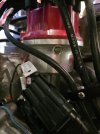
I wil look after it.Bart, in the documentation of my Accel DFI that pilote the ignition I found out that the designation should be a
MALLORY 77190M Firestorm Accel Dfi Dual Sync Distributor
The shape and connexion is exactly the one that I have
Thank you
I come back to keep you updated ; I ama seeing the end of the tunnel. I finsihed to put in place the windows and front light glasses. I was unable to renew the surfaces of the ones that I received with the car. They had scratches and even after repolishing with very fine grain and using various type of product the result was never acceptable. Finally I order part from Tornado, The thickness is much less than the ones coming from RCR and they seems to be very sensitive to scratches.


Now I am working on the oil circuit, I am waiting some parts to equiped the engine with a oil radiator and an Accusump. The Accusump and its valve are in place.

I modified also the seat to allow an easy deassembling of the back and give a quick access to the engine bay, and to be compatible with a 6 point harness.


Engine is running, at this time in the garage, I had a hard time to put the good parameters on the Access DFI7 injection, but with a little help from the creator of this device George Landis, I finally get to it. Now I should go a spped shop that has a roller bench to optimize the adjustment.
My last problem a t this time is the height adjustment. To I tried to adjust the front to 110mm, 4.3" but when I am doing this the spring is not fully compress if I lift the front on a jack and I wunder what would happen on a track if the suspension is completely decompressed like it is on a jack.
The ressort is not compressed anymore if I reach a height of 160mm 6.3". Is there a problem some where, should I put a spacer, or change the spring length? Any idea ?

Now I am working on the oil circuit, I am waiting some parts to equiped the engine with a oil radiator and an Accusump. The Accusump and its valve are in place.
I modified also the seat to allow an easy deassembling of the back and give a quick access to the engine bay, and to be compatible with a 6 point harness.
Engine is running, at this time in the garage, I had a hard time to put the good parameters on the Access DFI7 injection, but with a little help from the creator of this device George Landis, I finally get to it. Now I should go a spped shop that has a roller bench to optimize the adjustment.
My last problem a t this time is the height adjustment. To I tried to adjust the front to 110mm, 4.3" but when I am doing this the spring is not fully compress if I lift the front on a jack and I wunder what would happen on a track if the suspension is completely decompressed like it is on a jack.
The ressort is not compressed anymore if I reach a height of 160mm 6.3". Is there a problem some where, should I put a spacer, or change the spring length? Any idea ?
I hope you are leaving the 8 stack. And I see you moved the shifter to the proper side.
Hi Jean, in the States the fuel intake system you have on your engine is typically called an 8 stack for the 8 individual carb or injectors. Usually Borla on Inglese brands or a few others. I have an RCR on order but wont be getting it until late next spring early summer.Sorry Mark I miss the meaning "you are leaving the 8 stack" ? I am french, could you clarify ?
try these to stop spring un-seating
 www.merlinmotorsport.co.uk
Jerry
Helper Springs for Coilover Suspension from Merlin Motorsport
Quality parts, spares & racewear for all Motorsport needs. Huge stocks supplied worldwide. Fast delivery. Professional service. Call us for technical help
Jerry
Ok Mark, yes its a 8 stack Brola first generation, it the reason why it was equiped with Accel electronic that no more exist because purchased and replaced by HolleyHi Jean, in the States the fuel intake system you have on your engine is typically called an 8 stack for the 8 individual carb or injectors. Usually Borla on Inglese brands or a few others. I have an RCR on order but wont be getting it until late next spring early summer.
Jerry, thank you so a spacer is required.
I kept my old windows htat are already shaped to be able in the future to use them as master for mold.looking nice! Don't forget the wiper blade ;-).
In future, now that you have their basic shape, you can form/cut the light covers yourself!
Randy Folsom
Supporter
For your coil overs. Drill holes in the hats and secure the hats to the springs with zip ties. This guidance comes from the Factory Five Racing Roadster (Cobra) build manual. On the FFR forums some builders recommend using Stainless Steel zip ties.I come back to keep you updated ; I ama seeing the end of the tunnel. I finsihed to put in place the windows and front light glasses. I was unable to renew the surfaces of the ones that I received with the car. They had scratches and even after repolishing with very fine grain and using various type of product the result was never acceptable. Finally I order part from Tornado, The thickness is much less than the ones coming from RCR and they seems to be very sensitive to scratches.
View attachment 149950View attachment 149951
View attachment 149952
Now I am working on the oil circuit, I am waiting some parts to equiped the engine with a oil radiator and an Accusump. The Accusump and its valve are in place.
View attachment 149953
I modified also the seat to allow an easy deassembling of the back and give a quick access to the engine bay, and to be compatible with a 6 point harness.
View attachment 149955View attachment 149956
Engine is running, at this time in the garage, I had a hard time to put the good parameters on the Access DFI7 injection, but with a little help from the creator of this device George Landis, I finally get to it. Now I should go a spped shop that has a roller bench to optimize the adjustment.
My last problem a t this time is the height adjustment. To I tried to adjust the front to 110mm, 4.3" but when I am doing this the spring is not fully compress if I lift the front on a jack and I wunder what would happen on a track if the suspension is completely decompressed like it is on a jack.
The ressort is not compressed anymore if I reach a height of 160mm 6.3". Is there a problem some where, should I put a spacer, or change the spring length? Any idea ?
View attachment 149957
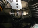
Thank you Randy, it is a good idea, but a friend, engineer on Michelin tires for Le Mans racing car told me that they use "helper spring" on racing car especially to keep the spring in place when you lift the car on a jack. It also what Jerry suggest. The spring have almost no impact on the stifeness of the main spring and is very small when it compress. On top of it is rellatively cheap.
Helper springs are in place. It was necessary to cut the centering ring that goes between the regular spring and the helper spring to allow the complete compression of the helper spring in compress position.
Now I am finishing the oil circuit, Accusump + radiator but some fittings were missing and I should finish it next week. I order my fitting to Torques UK, for me an excellent vendor.
In the meantime, assembly of the rear tow ring; I had to attach it to the main chassis because the rear subframe is only there to support the rear hood and didn’t seem rigid enough to be a good towing point.

To continue to work I tried to adjust the suspension. Not an easy task. I adjusted the height first about 4 inch front and 5 inch back.
After a lot of other little details, I started trying to get close to the suspension settings. By searching on forum, I made a choice that I will try to approximate before putting it on a test bench or on a track.
Front per side
Toe +0,07° = 0,5mm on 414mm wheel
Camber -0,8°
Caster +5,0°
Arrière par roue
Toe +0,1° = 0,7mm
Camber -0,8°
Caster +6,0°
Some oddities, the toe values are very low, almost zero. Another thing, a caster value for the rear – I think this refers to the spindle inclination angle since, obviously, the rear axle is not steerable.
I adjusted the front, except for the caster which I haven't done yet, and I'm almost at the correct values. A bit annoying because you have to remove the upper ball joint each time to adjust the camber. But after 3 removals, I'm at the correct value.
For the hunt, it will be worse; it seems to me that I will need to get it by adjusting the lengths of the two ball joints on the upper arm. So I’ve put it on hold for now, knowing that it’s not easy and I need to dig deeper. If I understood correctly, I need to measure the inclination angle of the front suspension before and after rotating the steering knuckle by 20°.
So I started on the rear suspension; that’s more complicated. I’ve made a basic schematic, see PDF
The camber is practically at the correct value, and I should be able to adjust it with the C link. My problem is the toe; it is far from the correct value, and I tried to fix it with the D and E links (tie rods), but both are at their limit, and moreover, they are supposed to be used for adjusting the caster. So in my opinion, only the two ball joints, A and B, remain, which should allow me to adjust the toe.
What’s your opinion?
Now I am finishing the oil circuit, Accusump + radiator but some fittings were missing and I should finish it next week. I order my fitting to Torques UK, for me an excellent vendor.
In the meantime, assembly of the rear tow ring; I had to attach it to the main chassis because the rear subframe is only there to support the rear hood and didn’t seem rigid enough to be a good towing point.
To continue to work I tried to adjust the suspension. Not an easy task. I adjusted the height first about 4 inch front and 5 inch back.
After a lot of other little details, I started trying to get close to the suspension settings. By searching on forum, I made a choice that I will try to approximate before putting it on a test bench or on a track.
Front per side
Toe +0,07° = 0,5mm on 414mm wheel
Camber -0,8°
Caster +5,0°
Arrière par roue
Toe +0,1° = 0,7mm
Camber -0,8°
Caster +6,0°
Some oddities, the toe values are very low, almost zero. Another thing, a caster value for the rear – I think this refers to the spindle inclination angle since, obviously, the rear axle is not steerable.
I adjusted the front, except for the caster which I haven't done yet, and I'm almost at the correct values. A bit annoying because you have to remove the upper ball joint each time to adjust the camber. But after 3 removals, I'm at the correct value.
For the hunt, it will be worse; it seems to me that I will need to get it by adjusting the lengths of the two ball joints on the upper arm. So I’ve put it on hold for now, knowing that it’s not easy and I need to dig deeper. If I understood correctly, I need to measure the inclination angle of the front suspension before and after rotating the steering knuckle by 20°.
So I started on the rear suspension; that’s more complicated. I’ve made a basic schematic, see PDF
The camber is practically at the correct value, and I should be able to adjust it with the C link. My problem is the toe; it is far from the correct value, and I tried to fix it with the D and E links (tie rods), but both are at their limit, and moreover, they are supposed to be used for adjusting the caster. So in my opinion, only the two ball joints, A and B, remain, which should allow me to adjust the toe.
What’s your opinion?
Attachments
My .02 worth having built an RCR40 ::Some oddities, the toe values are very low, almost zero. Another thing, a caster value for the rear – I think this refers to the spindle inclination angle since, obviously, the rear axle is not steerable.
What’s your opinion?
Clearance for The upper rear control arm you identify as “C” is a key reason to get the rear (correctly stated) inclination angle moved toward what would normally be thought of as positive castor. Also in consideration is achieving the 95” wheelbase and/or centering the wheels within the arches..
I just mount my new tires. The Avon historic CR6ZZ delivered with the car were 12 years old and completely dry, even if they never saw a race track.
After a lot of considerations I bought Nankang historic CRV6 from Nakang Nederland in exactly the same dimensions than the Avon. My total cost was 2000€, 400€ less than the Avon for 215/60x15 front and 295/50x15 back, that guide my decision.
For the back no problem but for the front they are a little bit higher in diameter, about 1/4".
The result is when I turn the front wheel they are coming very close to the lower side of the body. Anyway I have to reajust precisely the height. But I will may be try to move the upper triangle forward. I do not have a lot of adjustment only one washer left. If it remain to close, I will have to cut in the glassfiber of the bottom sides.
What do you think ?
Attachments

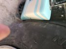
If you have problems in the straight position of the wheels (photos) how do you envision turning them under steering? A while ago I test-fitted 225/60 Avons which I use on another car - I had the same problem as you and went back to my 215/60R15. I think the only choice is to move the front suspension forward as much as necessary. On my RCR the front wheel sits slightly to the rear of the wheel arch so this would be feasible.
Similar threads
- Replies
- 10
- Views
- 1K
- Replies
- 14
- Views
- 2K
- Replies
- 7
- Views
- 970