rear suspension idea

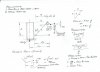
gentlmen your collective thoughts please, i have been trying to figure out how to get the rear suspesion set up to fit and to work, as room is not plentifull
after a lot of messing around with cardboard ive come up with this idea,
2008-10-11-2214-16_edited.jpg


i will get the push rod travel figure tommorow [i forgot] but other wise it will all fit ok.
can some answer the 2 questions
bell crank ratio [ ithink its 2-1]
spring rate required for 150kg per cnr [rear only]
opinions please
cheers John
 
Certainly looks fine, though the 30 degree push rod angle implies reduced displacement with wheel travel.

I assume a pull rod set up won't fit.
 
Last edited:
Hi mate, i did look very seriously at going a pull rod set up but it would have involved even more headaches.
the 30 deg angle on the push rod gives me 40mm travel from bump to droop, and that multiplies through the bell crank as per sketch, to 65mm shock travel, more than enough.
all i have to try and work out now is my spring rate needed to hold up 150kg per cnr
any Math geniouses out there, i'm hopeless
cheers John
 
Going to be an extreme rising rate as you have drawn it John.
Lets assume that you have the drawng at ride height with the damper assy at approx half compression- then the chassis pivot should be @ the same height as the top damper eye & at 90° to the damper c/l. Included angle of rocker should then be opened out so that pushrod is also closer to 90° ( depending on whether you still wish to have rising rate.)
Rocker could be made with adjustable pushrod position to allow fine tuning in this area without major rework.
 
thanks for the input Jac, the problem is the position of the chassis rails as per sketch, i could possibly lift the push rod over the top of the top rail but i dont have a lot of clearance under the body work in that area, if it stays original, 60-70mm max, thats the biggest problem, its giving me one helluva headache thats for sure, i tried to set it up as outboard but the shock angle would be 50 odd degrees and i'd need 2000 lb springs, so it will have to be inboard, hence its sitting down with carboard cutouts trying to get it right

Terry, mate i not long ago finnished another mock up and almost mirored your design and it looks much better, also the arc that the top shock mount travels through is a fraction of my first idea 50mm on 1st to 15mm on 2nd design.
with those figures in sketch what would the correct rocker ratio be
appreciate the help guys
cheers John
 
Last edited:
John,where does the damper eye sit at desired ride height compression in relation to the height of the frame rail pivot point - any picture available?
 
Last edited:
john, you could always turn the dampers so they sit along the top of the transaxle ala current single seater practise etc. Gotta go, some serious non monetary news on TV about now:)
 
Al that has yet to be worked out, as far as i can work out the shock top pivot would need to be as close to parralel a pos with the chassis pivot point as in Terry's diagram
cheers John
 
Yep thats along the lines I'm thinking, John will probably get on board with that idea as well after watching Bathurst from the couch today- nothing like a bit of horizontal thinking to clear the cobweb's.:)
 
So in order to balance the leverage around the static ride height, it would be as such?

standard.jpg

Terry, I think the picture you show is where maximum rate is reached.
My thought would be that this point i.e. the right angles, should be reached at max bump or after, so as to make sure the suspension doesn't go into a falling rate situation.

Kaspa, I'snt the first thing you need to decide on the target suspension frequency and from there work back through the geomtry to find out the required spring?
 
first off what an amazing finnish to a 6hr enduro, and the best part Craig and a FORD one and i picked it, and Greg was a brilliant 2nd.

now while all this was going on ive been busy with my cardboard computer suspension anyliser, and have come up with what i think is as close as Damn it is to swearing
the 20mm height shown, is the shock mount position above the chassis pivot point at static ride height, which will decrease to 10mm below the centerline at full bump.
2008-10-12-1747-59.jpg

Jac i put a afair bit of thought into trying to mount the shocks on the trans as you sugested but for a number of reasons i didnt think it was the best option, what i have come up with gives me a moderate rising rate that can, and will be adjustable, keeps the shocks out of harms way and nice and low in the chassis, and will be simple to engineer , which is good as i dont have access to much equiptment
opinions greatfully welcomed as allways
thanks John
 
Your rocker ratio is actually 1.66/1 and with 40mm pushrod travel your shock will compress by about 66mm. In order to figure out the spring rate I imagine the boffins on this site will want a measurement of wheel travel to pushrod travel- preferably from static ride to bump & droop heights as your pushrod angle means that wheel and pushrod travel rates wont be linear.
 
Picky b@gger, it was close enough for me.
sorry Jac i forgot to put that in , i worked on 3inches of wheel travel or 75mm fom bump to droop= 40mm pushrod travel = 66mm of shock travel, roughly the same , give or take a mill or to, as the front.
and the push rod angle is now 38 deg by going over the top of the rail.
one other point which may or may not influence anything, the push rod is mounted on the REAR bottom cnr of the uprite, as i cant get it on the front because of suspension arms , mounts, drive shafts etc, god knows i've tried.
john
 
Last edited:

Trevor Booth

Lifetime Supporter
Kaspa,
you need a few more dimensions and then you can work it out.

The use of a bell crank (rocker) provides a rising wheel rate not a rising spring rate unless the spring is wound with varying pitch or diameter or tapered wire (or a combination of all 3)

Note that i have assumed that the pushrod to bell crank angle is 90º and that the shock is vertical, the calcs are not valid if this is not the case. The dimensions Lp and Lw are the effective lengths about the pivot of the lower wisbone, ie they are measured at 90º to a line drawn thru the lower inner pickup and the pickup of the forward end of the lower trailing arm (radius rod)
 

Attachments

  • rear pushrod calcs.jpg
    rear pushrod calcs.jpg
    28.5 KB · Views: 456
Trevor thanks for your time mate appreciate it immensly.
went out to the shed with trusty protractor and level and this is as about as accurate as i can get, I hope its enough info for you
shown at static ride height
2008-10-13-1924-42_edited.jpg

note the bottom shock mount is shown tilted in to chassis rail but can be mounted pepindicular if preferred.
many thanks John
 
Last edited:
How about laying the shocks flat, but in a 'north/south' configuration along the lenght of the chassis, not across it.
Can I be even more forward and say how about a torsion bar for springing?
 

Trevor Booth

Lifetime Supporter
Kaspa,
that is a start, please provide the dimensions o, a, h as per my sketch.

the purpose of this exercise is for you to learn and understand. Quite happy to do it for you no probs, but you will not learn and understand if I just say " do this" It is very simple in fact to work it out. It all works on the "crow bar" principle

once the loads are calculated we can then get into springs and things
 
Back
Top