Roaring Forties #36 Joe's Completion Log

Bill Hara

Old Hand
GT40s Supporter
Mark you are making astounding progress, you have taken the bull by the horns....

I seem to be working the other way around to you, body first then mechanical, I do know that I am having to be very careful around the paint surface....

Just a question on your last post, the brake line bleeder for the rear is directly under your adapter plate and like mine faces upwards. Can you tell me if there is enough room to bleed the brakes line or would you consider adding an extension piece that would turn the bleeder through 90 degrees?

Thanks

Bill.
 
Thanks for your kind words, Bill. The top of the bleeder fitting is close to the bottom of the transaxle case, probably 1/4" or less. I still think you could get a rubber hose on there without kinking though. Might make sense to cut the fitting bown to one barb.
 
Your plumbing puts mine to shame! Very nice. I had the same problem with my pipes, only mine came from RF. They were not pretty, so I had no problem cutting and welding to get them to fit up. Your work looks fantastic.
 

Ron Earp

Admin
Nice work!!!

I experienced your pain with Custom Metal Werks exhausts too. I had two of them from George, neither were identical, and one much better than the other. Have a look on this thread, maybe some of those pictures might help:

http://www.gt40s.com/forum/showthread.php?t=12113

One set was really tight and nice, the uncoated ones, and those I sold with the car. The other set was okay, but needed some tweaking. I'm pretty sure that:

You + Buddy + Beer + Torch + Iron bar = Aligned pipes

I'd recommend to use two separate mufflers on the crossover exhaust instead of the single - the certain sound works and doesn't get muffled and lost.
 
Thanks, guys. Ron, I have also considered two mufflers (Borlas) but I'll try the Custom Metal Works resonator that I have before I decide to upgrade.

A couple weeks ago I purchased a set of rear drag links from a forum member; these pieces were really nice, made from 4130 with beautiful tig welds on the 4130 threaded tube caps, with the ends having both left- and right-handed threads. So adjustment is a simple matter of loosening two locknuts, and spinning the link one direction or another.

I took these pices, along with some others, to a nearby plating shop where they were electroless nickel plated. I got them home and into a 375 * F oven about an hour after the parts left the plating bath, and I did a full 5-hour embrittlement relief bake on the parts. The other stuff I had plated were the transaxle brackets, the door striker plates, the gear shift linkage bracket that bolts to the transaxle, the rear end of the front shift rod, and the external portion of the modiified transaxle selector shaft. The shaft was somewhat corroded just from sitting around so I figured nickel plating would inhibit corrosion. The reason I did the rear portion of the front shift linkage rod was because that is something Carrol Smith recommends in one of his books - nickel plating on the part of the shift rod that passes through a rod end to minimize corrosion and to allow smooth movement of the linkage without use of oils or other lubricants which would otherwise attract grime and potentially foul the linkage.

Here's a picture after everything came out of the oven. Now I have a bag full of new 5/8" rod ends so I'm going to go out in the garage and play with the suspension.

Nickel%20plated%20parts.jpg
 
Last edited:

Dutton

Lifetime Supporter
Mark -

That's probably the nicest workbench I've ever seen... that's not granite, is it? ;)

If it takes as many years as you have into your GT to arrive at this level of finish, it's well worth it.

Tremendous work, man.

T.
 
Well, it has been quite a while since I've had much to add, but I have made some progress of late.

First, here's my quick-release steering wheel setup. It is a spline drive, not hex, and it is retained by a ring, not pins. It is well made and cost me about $55. The second photo shows it as viewed from the mounting location for my Moto Lita steering wheel. Obviously, a new adapter was required to make it work.

I enlisted the assistance of forum member CharlieM, who has access to a lathe and who fabricated for me the adapter shown in the third picture. Charlie also measured the taper on my steering column shaft and cut and turned the inside of the Winters spline to match. No need to weld - Charlie found a way to keep the original retaining bolt and simply pin the spline to the column. First-class work by Charlie - it turned out beautifully. Thanks, Charlie!
 

Attachments

  • IMG_0587.jpg
    IMG_0587.jpg
    51.3 KB · Views: 893
  • IMG_0592.jpg
    IMG_0592.jpg
    37 KB · Views: 899
  • IMG_0761.jpg
    IMG_0761.jpg
    53.6 KB · Views: 957
Last edited:
I've also been kicking up some dust.

First I sat in the car and had my brother line up the bubble for my driving position and trace its outline. I made a little jig to transfer that line to the inside to show the cut out area. The next photo shows my youngest son, Luke, laying into the driver's side (right-hand side in my case) door roof to allow cutting out of the Gurney bubble hole. We cut it out with a jigsaw and tested the fit. Then, working on the inside of the door, I scribed the outline of the flange, and used a Dremel and broke several of the fragile little cutoff wheels to relieve the inside fiberglass skin. Finally, I sanded to final shape. Next I need to lay some fiberglass to seal up the gap on the inside. I decided to screw the bubble on from the top, like the originals. It also provides a little more room mounting it this way rather than fiberglassing it in.

Note the foam filler between the inner and outer roof skins. On Hershal Byrd's advice, I got a few cans of Dow "Great Stuff," Doors & Windows variety, drilled a few strategic 7/32" holes in the spider and doors, and injected the foam into the cavity. The reason I did this was to improve the thermal insulating properties of the bodywork, improve their rigidity, and hopefully keep things a tad quieter in the cockpit. Total cost - about $10 and maybe 2 pounds of cured foam.

Much sanding and paint prep work is happening now, and I hope to start spraying primer in August. I'm going to get as much body work and painting done as I can during the remainder of the summer and early fall, and then focus on getting the car wired and the engine started when the cold weather returns.
 

Attachments

  • IMG_0753.jpg
    IMG_0753.jpg
    23.3 KB · Views: 912
  • IMG_0757.jpg
    IMG_0757.jpg
    26.9 KB · Views: 917
  • IMG_0758.jpg
    IMG_0758.jpg
    33.5 KB · Views: 873
  • IMG_0765.jpg
    IMG_0765.jpg
    39.1 KB · Views: 930
  • IMG_0766.jpg
    IMG_0766.jpg
    84.3 KB · Views: 924
Last edited:

Chuck

Supporter
The foam filler is a nice idea, but was there any concern about it separating the fiberglass panels as it expands? Even with a few expansion holes, I would be concerned. I assume you did not have that problem? How close did you place the expansion / access holes and how large were they?
 

Fran Hall RCR

GT40s Sponsor
Mark,
its great to see your youngster taking an active roll in the car...my boy(6) has just started showing a real interest in all things tech...he even wanted me to show him how the CNC mill works ....great job.
 
I used the low-expanding variety of Great Stuff, made for doors and windows. There was no buckling or panel separation on my car. I injected it into the spyder from 3 or 4 locations, and into the doors from 3 locations each. The holes were just big enough to accept the plastic tube that comes with the foam can.
 
I've been making some progress on the body work lately. I'd like to get it primed and ready for paint in a couple months. The body work and paint represents that vast majority of remaining labor needed to get this car on the road, and I've found a local painter who gave me a quote of $600 to paint, stripe and clearcoat the car if I bring it to him with the body prep and primer done. That's a pretty damn good deal - I was getting ready to spend ~$400 just for a good spray gun for clearcoat. He wants to come out and see the car before I spray primer, so the goal I'm working toward is to have hime come over sometime in Feb or March. If I can get the car painted, then the rest should be downhill.

So I wanted to go into the New Year with a running start. I've been working on the car fairly steadily for the last few weeks, and making good use of my Reddy propane heater in the garage. I get the garage nice and toasty, and I go to town.

So here are some pics...

These are the Mental Performance hinges I got from Australia. Very nicely made from stainless steel, each hinge has a pin welded to a bracket that sandwiches the fiberglass mounting surface on the front and rear clips, and a piece that mounts to the chassis that accepts the pin. Bottom line - taking off the front or rear body work is now a 60-second task with two people.

attachment.php


When the old one-piece hinges came off this is what the fiberglass mounting surface looked like inside the rear clip. Note the multiple and oblonged holes from several attempts at mounting the rear body work. I was afraid that would let the body work move around so I decided to repair them.

attachment.php


Here I've used my trusty Makita disk sander to scallop out the edges of the holes to be repaired. After that was done I did a wet layup with some polyester resin and matt fiberglass to fill in the holes, then sanded flat after the resin had set up.
http://www.gt40s.com/forum/attachment.php?attachmentid=34950&stc=1&d=1230925264
attachment.php


Here's what the rear hinge pin and bracket looks like after the repair:


attachment.php
 

Attachments

  • hinge1.jpg
    hinge1.jpg
    32.4 KB · Views: 1,789
  • hinge2.jpg
    hinge2.jpg
    30.7 KB · Views: 1,673
  • hinge3.jpg
    hinge3.jpg
    33.8 KB · Views: 1,880
  • hinge4.jpg
    hinge4.jpg
    36.1 KB · Views: 1,633
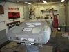
I spent the better part of two weekends with my brother last summer tweaking the fitment of the spyder and front clip, but nothing really picture-worthy. The mental Performance hinges changed the geometry of the front and rear clip mounting, so a lot of unsung work was done to get it right. More fitting, sanding, tweaking, removing, glassing, sanding, tweaking and refitting. I also enlisted a friend's help in refitting the rear clip with the new hinges. Everything lined up great when we finally drilled the holes in the repaired fiberglass for the new hinges, but then I noticed that the rear clip was not sitting flush on the body locating cones. More sanding, drilling, fiberglassing, re-drilling, sanding, and filling to get it fixed, but now it's done. Again, no pics from that exercise but many hours spent.

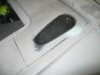
Still working on the rear clip. Next task was to find some acceptable latches for the rear clip to supplement the two latches that are often left open by overly exuberant GT40 owners. So a few weeks ago I ordered some Aerohinges from Coast Fabrication. I ordered the flush-mount variety because I'm a glutton for punishment. Hey, what's a little more fiberglass work? Here we go...

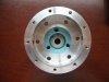
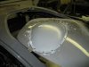
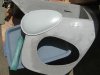
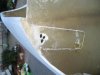
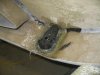
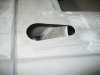
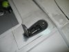
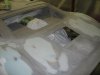
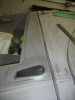
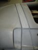
The Aerocatch latches come with cut-out templates that are used to mark the material to be gut. I decided to mount mine "backwards" on the rear clip in the same orientation as my Gurbey bubble. After checking to see if there would be adequate clearance for a bracket under the rear clip to catch the pin (there appears to be), I used the supplied templates to mark the location of the catches, drilled some pilot holes, and got the cut close with a jigsaw. Then I carefully used a carbide cutter in a die grinder and sanded to final shape. Here it is from above.

attachment.php


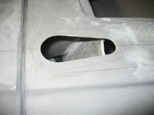
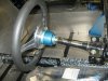
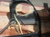
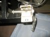
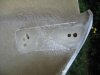
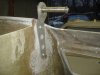
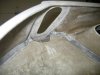
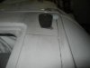
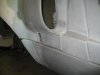
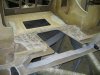
There's a bulkhead below that needed to be notched to allow the catches to be installed. Also, because the fiberglass body work is thicker than sheet metal for which the flush-mount Aerocatch is designed, I also had to carefully use the die grinder and a finish sander and hand sanding to grind down the thickness of the fiberglass from the inside of the rear clip. Nasty, tedious work, with glass fibers flying everywhere. Here's a view from underneath that shows what I'm talking about:

attachment.php


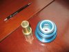
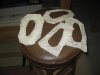
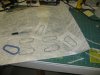
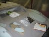
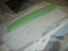
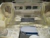
After I was satisfied with the fit of the latch in the rear clip, I cut out three progressively larger rings of matt fiberglass for each latch:

attachment.php


attachment.php


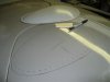
Then I got the garage nice and toasty, ran a bead of 3M 5200 around each mounting flange, then glassed them in.

attachment.php


May God help me if I ever need to remove or replace one of these bizznatches.
 

Attachments

  • latch1.jpg
    latch1.jpg
    27.6 KB · Views: 1,805
  • latch2.jpg
    latch2.jpg
    37.6 KB · Views: 1,669
  • latch3.jpg
    latch3.jpg
    65.7 KB · Views: 1,595
  • latch4.jpg
    latch4.jpg
    33.7 KB · Views: 1,615
  • latch5.jpg
    latch5.jpg
    39.6 KB · Views: 1,606
Last edited:
Here are the latches in all their glory. I still have to fab up some brackets to catch the pins, but that can wait until after paint. They're not quite perfectly flush - probably 1/64" or maybe 1/32" below the surface of the rear clip, but a quick chamfer on the edges with a small sanding block, some careful prep before paint, and I think they'll look great. I plan to keep them unpainted.

attachment.php


attachment.php


attachment.php
 

Attachments

  • latch6.jpg
    latch6.jpg
    20.9 KB · Views: 1,604
  • latch7.jpg
    latch7.jpg
    23.8 KB · Views: 1,607
  • latch8.jpg
    latch8.jpg
    18 KB · Views: 1,624
At this point I believe I have more than 200 hours into the body work on my rear clip. What a PITA. But I did a lot of things to that piece of fiberglass. I added Gulf flares, and spent countless hours with assorted sanding blocks trying to get the compound curve countours right. There were the latches I just described. I also removed the rear snorkels, and spent a lot of time trying to get the rear deck flat. After several sanding/filling events, I still wasn't happy with the surface when I ran my hand across the rear deck. So the other night I got pissed and spread a thin coat of body filler over each of the patched areas.

Here's a pic of the rear deck after I've laid out a thin patch of body filler on where the right snorkel used to exist. You can see several coats of filler on the left side which was filled a few minutes after this picture was taken.

attachment.php


Now I have both sides set up with a large, thin coat of body filler. I also put another skim coat along the flares. I opened the garage door for a minute to get rid of the polyester resin vapos and to take this pic - it's about 15 degrees outside and the heater was cranking. I'm going through over one tank of propane per week lately.

attachment.php


If you're not happy with the way a fiberglass surface feels, you won't be happy with the way it looks. The only path to salvation is a big-ass sanding block and fresh 80-grit sandpaper.

attachment.php


Here's how the snorkel patches turned out after they were sanded down. Not bad, and probably good enough, although a couple low spots will need a tad more body filler.

attachment.php


Next, I need to finish blending in the lower front of the rear clip into the side sills. Again, all this is necessary due to the Gulf flares. This is after at least 5 cycles of filling & sanding. I mixed up another couple batches of filler last night and it's waiting for me and my collection of sanding blocks this weekend.

attachment.php
 

Attachments

  • rear clip 1.jpg
    rear clip 1.jpg
    25.1 KB · Views: 1,689
  • rear clip 2.jpg
    rear clip 2.jpg
    41.9 KB · Views: 1,690
  • rear clip 3.jpg
    rear clip 3.jpg
    23.8 KB · Views: 1,561
  • rear clip 4.jpg
    rear clip 4.jpg
    22.9 KB · Views: 2,225
  • rear clip 5.jpg
    rear clip 5.jpg
    20.8 KB · Views: 1,554
You may notice how I've already added material to the bottom of the rear clip, but I still need to add more. Now that I'm almost done with the rear clip, I need to work the gaps between the panels to something acceptable. Right now the gap between the rear clip and the sill panel is too wide, so it needs fixin'. I'm also thinking about adding a couple layers of matt fiberglass to the forward edge of the rear clip because the gap between that and the rear of the spyder is a little over 1/4 inch. So I have to decide if the extra labor to fix it (maybe 5+ hours?) will be worth the improved look of the end result.

attachment.php


That looks a tad wide to me. Also, this, where the rear clip, sill, spyder and door meet, along with where the doors cut into the roof, is the trickiest part of the body work. That's next.

attachment.php


I also got the rear clip heat insulation installed. I spent a fair amount of time with a disk sander last summer getting the inside of the clip above the engine sanded down to a fairly flat surface to improve the adhesion of the insulation. You can see where the snorkel patches were filled in from below, as well as from above.

attachment.php


Here it is after the first sheet of insulation was installed. I'm still using Cool&Quiet from Lydell - the same stuff I've used on aluminum panels on the car. I'm going to paint the inside of the front and rear body work with Deltron DPLF, a flat black epoxy primer. I should be ready to shoot that pretty soon.

attachment.php


Last but not least I got the Honda S2000 engine start swiths fitted into my dash. It replaced the dash-mounted horn, and the horn is going to the steering wheel where it belongs. A friend has agreed to help me engineer a solution to this problem for my removeable wheel situation. He already helped me figure out how to wire it into the harness.


attachment.php
 

Attachments

  • rear clip 6.jpg
    rear clip 6.jpg
    15.8 KB · Views: 1,537
  • rear clip 7.jpg
    rear clip 7.jpg
    13.6 KB · Views: 1,571
  • rear clip 8.jpg
    rear clip 8.jpg
    42 KB · Views: 1,650
  • rear clip 9.jpg
    rear clip 9.jpg
    47.7 KB · Views: 1,698
  • dash1.jpg
    dash1.jpg
    46.8 KB · Views: 1,630

Chris Duncan

Supporter
"If you're not happy with the way a fiberglass surface feels, you won't be happy with the way it looks. "


Agree with that up to a point. I had what felt like waves on the top of my back clip, couldn't seem to get them out.

Ended up polishing the primer with polishing compound so you could step back and look at the reflection. Can't see any waves.

There are times also where there are waves you can't feel but show up visually, this is a way to see those before final paint.
 
I have a brand new set Front and back for half price if anybody is interested. These are a must.. if you own a RF!

John
 
Back
Top