Rufus GT-R

Car arrived, unloaded and in it's new home. Let the fun begin. Tape all removed and cleaned up. Inventory completed.
 

Attachments

  • IMG_1843.JPG
    IMG_1843.JPG
    212 KB · Views: 1,184
  • IMG_1846.JPG
    IMG_1846.JPG
    191.3 KB · Views: 1,165
Calipers are off for powder coating. Removed front end to relocate the splitter in the raised position. Following the instructions that H and Curtis have displayed on their builds. Removed tank for fuel pump modifications. Set the seat and steering wheel in to get an idea of location. The seat is a ProCar IMG_1859.JPGIMG_5362.JPEGIMG_1861.JPG
 

Kurtiss H.

Member
Supporter
Rufus, congratulations on the delivery of your car. Looking forward to following your build and sharing ideas.
 
Did the splitter relocation modification. I notched out the area for the tunnel cover then set some screws in to perform as stops so when I smeared the cat hair class on and bolted the splitter in place , the screws would keep from squeezing the splitter down tooIMG_1875.JPGIMG_1877.JPGIMG_1879.JPGIMG_1880.JPGIMG_1882.JPGIMG_1883.JPGIMG_1885.JPGIMG_1886.JPG much. After the cat hair glass cured I removed the splitter and filled in the void areas. I used a 3" X 3/16" flat bar as a guide to protect the offset. Sanded it smooth and is ready for paint. Flipped it over and cut through the glass only with a dremel tool then peeled the glass off. Then sanded the foam to shape. Used Bondo to help form the radius's then glassed over and sanded smooth.
 
All body panels removed now. Condenser mounted to radiator and in mock up position. laying out coolant lines to weld up. Ford says that engines will start shipping next week. It's taken as long to get the Aluminator 5.2 XS as it did the car!
 

Attachments

  • IMG_1939.JPG
    IMG_1939.JPG
    375.9 KB · Views: 698
  • IMG_1940.JPG
    IMG_1940.JPG
    341.3 KB · Views: 694
  • IMG_1942.JPG
    IMG_1942.JPG
    404.1 KB · Views: 871
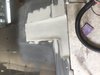
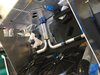
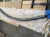
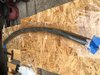
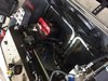
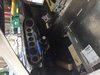
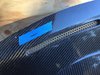
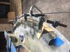
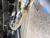
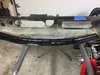
It's been a while since I've posted. I been working on the car almost every day. Make progress in areas and then wait for parts and move to another area. The splitter has been relocated to the top, fuel tank modified for the in-tank fuel pump system, all brake lines are remade and finished, brake, clutch and lift reservoirs are installed and connected, radiator and condenser installed, lift pump installed, water lined fabricated and installed and battery placed. Moving to the cockpit--access hole for the fuel pump and fuel level indicator cut, fuel tank, fuel pump and fuel level indicator installed. Electric power steering brackets fabricated and powder coated (will provide photos later- don't want them in the way for now). New RCR shifter installed and cables run to engine room. Now I am mocking up the dash to the spider checking for room for the defrost tubing to A/C unit Glassed up a trough using a metal rod and water pipe insulation as the shape. Matched the curve of the trough to the curve of the defrost slots in the dash and glassed it up. I will tab it on to the dash and make a transition to the defrost ports coming through the dash. The A/C unit is mounted and hoses run except for the 2 going to the rear.
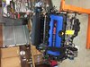
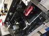
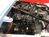
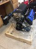
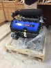
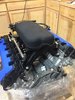
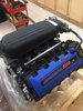
The Graziano is on its way to have the drop gears installed. Reversed the intake on the engine, mounted the A/C compressor and engine wire harness.
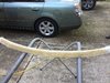
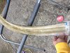
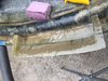
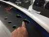
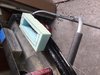
 

Attachments

  • IMG_1886.JPG
    IMG_1886.JPG
    269 KB · Views: 668
  • IMG_1940.JPG
    IMG_1940.JPG
    341.3 KB · Views: 642
  • IMG_2108.JPG
    IMG_2108.JPG
    483.5 KB · Views: 665
  • IMG_2140.JPG
    IMG_2140.JPG
    605.4 KB · Views: 576
  • IMG_2141.JPG
    IMG_2141.JPG
    608 KB · Views: 553
  • IMG_2149.JPG
    IMG_2149.JPG
    706.7 KB · Views: 521
  • IMG_2150.JPG
    IMG_2150.JPG
    679.8 KB · Views: 547
  • IMG_2153.JPG
    IMG_2153.JPG
    412.1 KB · Views: 531
  • IMG_2154.JPG
    IMG_2154.JPG
    410.7 KB · Views: 524
  • IMG_2155.JPG
    IMG_2155.JPG
    343.1 KB · Views: 599
Figure its time to post again. Been spending a lot of time finishing the defrost vents, throttle pedal linkage to FBW, The transaxle will be back from Ron McCall for the gear change tomorrow. Received the new oil pickup tube from MMR for the 5.2 engine and mocked up the new oil pan to the engine and found a problem. RCR has changed the front engine mount cross member --now the cross member is a 2X3 tube with 1-1/2 uprights. The cross member interferes with the oil pan and is made 1/4 inch too short. Will have to address these issues before I can marry the engine to the transaxle.
 
I trimmed up the defrost tube and fiber glassed it in place. The defrost outlets from the AC unit penetrate the top of the chassis and are flush with the top surface. (Restomod AC unit). I put the dash in place and located the area where the defrost duct will interface to the defrost outlets of the unit. I then made a duckbill to connect the two. There will be a foam donut connecting the two together. This similar to what H did. Before I glassed the tube to the dash, I glued the screens under the vent openings.
 

Attachments

  • IMG_2174.JPG
    IMG_2174.JPG
    491.2 KB · Views: 594
  • IMG_2176.JPG
    IMG_2176.JPG
    521.3 KB · Views: 525
  • IMG_2181.JPG
    IMG_2181.JPG
    530.6 KB · Views: 534
  • IMG_2182.JPG
    IMG_2182.JPG
    460 KB · Views: 493
  • IMG_2184.JPG
    IMG_2184.JPG
    438.9 KB · Views: 454
  • IMG_2185.JPG
    IMG_2185.JPG
    291.6 KB · Views: 449
  • IMG_2186.JPG
    IMG_2186.JPG
    496.9 KB · Views: 520
Back
Top