Rod C's Ohio RCR40

Well, here we go.
I order my RCR40 on February 2, 2023.
In late March 2024 I received the email from RCR that my car will be ready for pick up in early April.
I borrowed my neighbor's trailer, my son and I took April 15th off of work (1 day after my 50th birthday) and headed north to Detroit.

IMG_0720.JPEG

We had a little hiccup north of Marion OH when the awning on the trailer decided it wanted to open while traveling at 65MPH. In case you were wondering, an awning open while going down the road at 65MPH is not good on the awning. A pocket knife and some wrenches later, the awning was off the trailer and we were on the way.
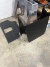
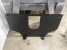
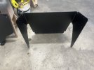
One we arrived at RCR, this is what we found...
At RCR 2.jpgAt RCR.jpg
We loaded it up, drug it home, unloaded it, and put it in the workshop.
IMG_0715.JPEGIMG_0712.JPEGIMG_0723.JPEGIMG_0731.JPEGIMG_0736.JPEG
Now the work begins.
 
Last edited:
First task to get done is disassembly. This thing is stuffed full of parts. Where in the heck am I going to keep all of this stuff?
First, off with the body
IMG_0737.JPEGIMG_0738.JPEG
Next, off with suspension
IMG_0776.JPEGIMG_0778.JPEGIMG_0780.JPEG
Another pile of parts to keep track of...I hope I took enough pictures and remember how it all goes back together.
IMG_0781.JPEGIMG_0784.JPEGIMG_0783.JPEG
Now to figure out where and how to store the body. I have to get this put someplace safe and out of the way until I need it.
 
Last edited:
I figured I could store the body on my 4 post lift & lift it up out of the way.
Here is what it looks like:
IMG_0785(1).JPEGIMG_0787.JPEG
Fran said to hang to doors by the A pillar
IMG_0790.JPEG
I supported the spider while resting on the roll bar - let me know if this looks concerning to anyone
IMG_0791.JPEGIMG_0793(1).JPEG
My NSX has been relegated to the bottom bunk & is getting to know the new stablemate.
IMG_0794.JPEG
 
Last edited:
With all of the bits and pieces removed from the chassis, I flipped it over and sanded the bottom and what may be considered wheel wells with 80 grit. This roughed it up for paint adhesion.
IMG_0795(1).JPEGIMG_0796.JPEGIMG_0797(1).JPEG
I then painted a coat of acid-etching primer and 2 coats of "Raptor" epoxy bed liner over everything I sanded. I used brushes and rollers rather than spraying. It seemed to go on well. The primer was a bit thin and runny while the raptor material is thick and sticky.
IMG_0798.JPEGIMG_0800(1).JPEGIMG_0801(1).JPEG
I used two bottles of the raptor material & have two left (bought a pack of 4). I need to cover the front radiator mount sheet part and the rear diffuser. I will also likely coat the backside of the firewall. I may use any remaining to undercoat the rear and front clam shells.
Now I wait for the 7 day cure.
I am not sure if I will paint the top side of the chassis. I will see what it looks like when I flip it over. I will dynamat the cockpit to help with noise and temps.
I will work on the fuel tanks while the epoxy cures.
 
I have my chassis flipped back over and have begun working on the fuel tanks. I have been working on my aluminum welding skills, which need improvement. I have built and added mounting brackets to both tanks. My tanks will bolt in, 2 bolts on each end, through the bottom of the pontoons. My tanks will sit on three 1/2" rubber pads and have rubber padding on the right and left side as well. I am going to give them a firm but cushy ride. I have also added return 1/2" npt bung to each tank. No issues really through all of this process.
The issue I have run into is my fuel lever senders (holley lidar based technology that came with my RCR kit) use the standard SAE pattern for fuel level senders. The pattern in my RCR tanks has the 5 mounting hole equally spaced, which does not match the sender unit. Only 3 of 5 holes line up. I know...they only fit one way, as one of the spacings is larger than the other four. I have rotated and rotated and rotated and rotated and rotated and they simple do not line up in any rotation. I even tried each sender in each tank. Eventually I got a bit smarter and measured. The patterns do not match. The tank has a equally spaced pattern and the sender is the SAE standard.
My plan is to enlarge two of the holes on the tank and plug them with a 3/8 aluminum rod (maybe thread the rod and the hole & loktite them in). I will then drill and tap the plugs at the appropriate pattern and then install the sender units. I need to enlarge the existing holes so the new holes are completely in the plug and not partially in the plug.
I feel like this is the 1st of many to come hiccups in the build process. Keep focused, take my time, think through multiple solutions, pick the right one, execute, repeat. I will include some pics soon.
 
It has been a few weeks since I have provided any updates. It seems job and family obligations are going to be disruptive to my GT40 building efforts. Anyway, I have been working on fuel tanks and undercoating.
After a few attempts of drilling, tapping, loctiteing and plugging the incorrect fuel level sender pattern, I realized that plan was not going to work. I could get them plugged, but drilling and tapping caused the loctite to release and the plug screwed down into the tank, not good. So I eventually made solid plugs, welded them in and sanded everything smooth & flat. Drill and tap and my fuel level senders now install as they should.

IMG_0827.JPEGIMG_0832.JPEGIMG_0833.JPEG
While messing with the fuel level senders I went ahead and calibrated them with the gages and marked which is driver side and which is passenger side. One could probably mix and match, but why take the chance? Both sides seem to work correctly and measure level correctly, a win!
I welded on some mounting brackets to the front and rear of each tank. Each tank will be bolted through the bottom of the pontoon, two bolts on each end. I had to create some access holes in the end of each pontoon to reach the bolt heads.
IMG_0831.JPEGIMG_0830(1).JPEGIMG_0837(1).JPEG
I also welded in return line 1/2 NPT bungs to each tank. I will add another post with my fuel system plan.
IMG_0829.JPEG
I opened up an access panel at the rear on each side. I made covers for each panel.
IMG_0835(1).JPEGIMG_0836.JPEG
I glued in 1/2" rubber pads under each tank, 3 on each side.
IMG_0834.JPEG
I believe I am ready to finally insert the tanks 1 more time and bolt them down. I am probably wrong in this belief, but we gotta have goals.
 
Last edited:
I also printed a simple alignment tool to ensure the fillers on the tanks line up with the filler hole in the chassis. I plan to use 3D printed tools, fixtures and even parts throughout my creation. This tool has an ID that matches the filler on the tank and an OD that matches the chassis. This will ensure centering when I bolt in the tanks.
IMG_0838.JPEGIMG_0839(1).JPEG
 
Since it was REALLY nice here on Saturday I took a break from screwing with fuel tanks and raptor coated the front radiator support part and the rear part. I sprayed these instead of rolling on the material. They seem to have come out well. Now they are ready to go back on the chassis.
 

Attachments

  • IMG_0840.JPEG
    IMG_0840.JPEG
    326.3 KB · Views: 96
  • IMG_0841.JPEG
    IMG_0841.JPEG
    527.4 KB · Views: 94
  • IMG_0842.JPEG
    IMG_0842.JPEG
    610.6 KB · Views: 92
Fuel System Plan - I will be using a Holley Sniper 2 Fuel Injection system on a 347 for my car. I will use Holley's ignition, coil, distributor, timing control, ect.
I put one of these system on the mopar 400 in my '57 Dodge pickup and love it. Big block mopars love a lot of timing, especially if compression is under 10:1. Holley's system allows me a create timing maps and load them in fast and easy. Get in, turn the key, pressure the fuel system and it starts right up. I really like the system & so does my old truck.

Anyway, this GT40 will be fuel injected, so I need high pressure fuel to the Holley system. My plan is to pull fuel from each tank with it's own Facet Dura-Lift low pressure pump (2 facet pumps total). Filters and check valves are part of these pumps, so ease of use for the win. These pumps will be controlled via a single double throw (on-off-on) switch, so only one side is on at a time. Both Facet pumps will be plumbed to a single swirl pot. The swirl pot overflow will return to the passenger tank, which will be my main use tank. One will normally drive with the passenger side facet pump filling the swirl pot. When the passenger tanks gets low, I will switch from the passenger side facet pump to the driver side facet pump. This will fuel the vehicle and transfer fuel to the driver tank simultaneously. Once the passenger tank is full or the driver tank is empty, switch back to the passenger tank fuel pump and carry on.

I believe the only risk with this plan is overflowing the passenger fuel tank. If there is already fuel in the passenger tank & I run off of the driver tank too long, the passenger tank will over flow. I can manage this risk by only using the driver tank when the passenger tank is near empty or only transfer fuel while I am sitting still and focused on fuel transfer.

I am also considering using a timed push button switch to trigger the driver tank pump. In this scenario I would always drive from the passenger tank and the passenger tank pump will always be running. If the passenger tank gets low, push the driver tank button, triggering the driver pump to run for a period of time (say one minute or whatever) then it shuts off. I could set the timer so 1/2 or 1/4 of the driver tank is transferred with each button push. This way overflow risk is minimized, only push the button when the driver tank is low, and I won't forget to switch the pumps.

The swirl pot plumbing is straight forward. The high pressure pump will feed the Holley Sniper, which will return to the swirl pot. The swirl pot overflow will return to the passenger tank as stated above. I want to use hard aluminum fuel line with 6AN ends as much as possible, likely using flexible to and from the Holley Sniper body.

I have seen fuel systems discussed over and over on this forum. Input, ideas and thoughts are welcome.
 
Last edited:
I continue to plug away putting this car together. I have my fuel tanks installed and bolted down. Nothing real exciting there.
I have installed the suspension, front and rear, set everything back on the ground and dialed in the alignment fairly close. I do not have a steering rack yet, so setting front toe is not possible, which makes a wheelbase measurement not quit accurate. Currently I am setting around 95 3/8 on both sides. I could bring the rear in a bit since my lower trailing arms are threaded out a little (few turns). See my first concern below as another potential to shorten wheelbase.
I have few areas of concern I hope others may be able to help me with.
1.) My fronts are not set with bottom A-arm to the front and top A-arm to the rear. My tops are toward the front and bottom are towards the rear. This has given me 5deg of caster. I would have to figure something else out to reduce the caster. This is opposite of most of what I have read.
IMG_0905(1).JPEGIMG_0906(1).JPEG
2.) My front driver side suspension is noisy. It squeaks with up and down movement. I did get in the tub and grind away some weld ends and interference to improve the connection for the top A-arm brackets. They were not sitting flush due to interference inside the tub with welds and such. Improving these mounting surfaces did not help. Could this be because everything is not torqued to spec yet? Specifically the lower A-arm bolts inside the tub?
3.) The lower trailing rod connection is really close to the rear wheel. I am concerned with any in/out movement causing this connection to cut a rear tire. I do not want to cut a rear tire. Should I worry about clearance here? How much clearance should I have?
Picture here shows the area I am describing. I will post a picture of the actual gap later today.
IMG_0751-1.JPEG
4.) I tried to keep the trailing rod connecting brackets at the rear tire 'vertical'. This made it difficult to connect everything, so I let the rotate a bit. Should I worry about these being vertical, or just let them rotate as long as they do not bind? Again, picture to show the area I am describing.
IMG_0741-2.JPEG
I am beginning to set on the body & will post about how that process is going.
 
I put my roll cage back on, along with the rear bulkhead. When I tighten everything down, the bulkhead 'bar' between the rear window and lower bulkhead access panel would bow, quite a bit, more than an inch. I tried to slot the bulkhead between the front and rear cage connection with no success. I then noticed the trailing rod connection covers by the rear bulkhead stuck into the cabin past the bulkhead. There was no way I could have installed the lower access panel. The rear bulkhead was out of whack once all connected. If I removed the screws at the bottom of the bulkhead into the tub I could get the bow to go away and maybe get the lower access panel to fit. I have installed a 3/8 thick spacer along the edge of the tub where the rear bulkhead connects. Everything fits a better now.
I am terrible at taking pictures as I go. I will add a few pictures here to help every see what I am talking about.
 
I started body fitment with rockers and the spider. The edge of my rockers was far from horizontal when placed on the chassis and even further from being flat.
IMG_0897.JPEGIMG_0895.JPEGIMG_0896(1).JPEG
I tried to heat and adjust with no success. I decided to remove the edge and glass in 1 1/2 x 1/16 aluminum bar. I fixture this to be parallel with the bottom edge and straight/flat. I figured the aluminum would make for a stronger top surface for mounting, body pins, etc. I have some gaps to fill and body work to do, but overall they cam out looking pretty good.
IMG_0900.JPEGIMG_0901(1).JPEGIMG_0902.JPEG
I will attempt to fit them to the car this evening.
 
Last edited:
My spider does not fit to the cage for crap. It is not symmetrical from right to left. I was afraid the spider was way off, but took to measuring the cage to the chassis first.
(1) The two overhead front to rear bars of the cage are shifted towards the driver and are not in the center of the chassis.
(2) My front hoop has a bit of fore/aft curve along the top "straight" part, especially on the passenger side
(3) Passenger A pillar cage point is more outboard on the bracket while the drive A pillar cage point is centered in the bracket.
(4) I needed to trim the spider at the bottom of the A pillar due to cage interference.
What is really odd is the overhead bars are shifted toward the driver while the front hoop of the cage seems to be shifted toward the passenger side of the car. I do not believe any of this is the end of the world or has any functional impact. It certainly does not look right from the front of the car.
IMG_0890.JPEGIMG_0891.JPEGIMG_0892.JPEGIMG_0893.JPEG
 
Back
Top