Thanks James, how does the release rod get installed up into the roof section so that you can release it from the small rectangular hole in the center of the rear of the roof?
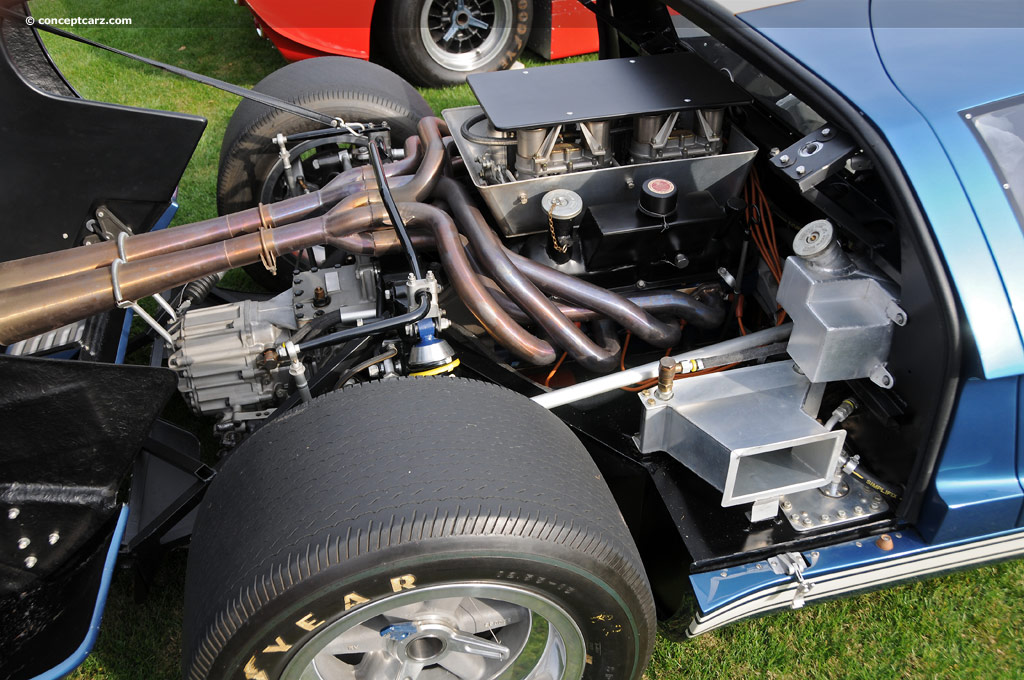
I can see the rod coming down and entering the side of the slam catch in this photo.

Also note the rear accelerator cable attachment, the braded heat shield, the slight downward bend in the end of tray above the intakes, and the marks in the white stripe on the roof return as well as the dings in the flanges and slam catch mounts.
Trying to work out if this is 104 or 103.
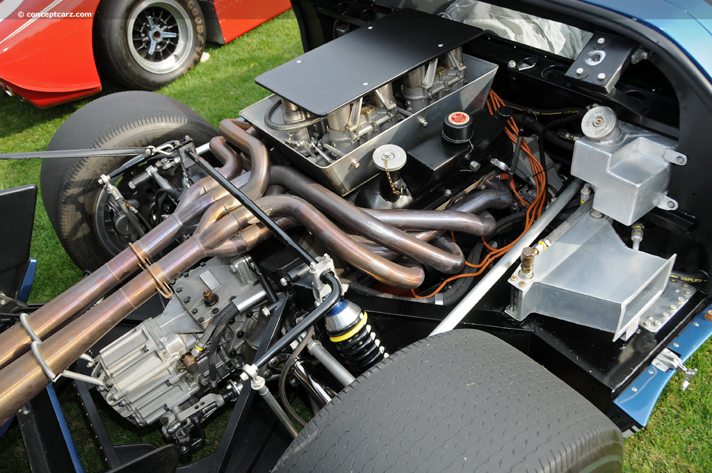
I can see the rod coming down and entering the side of the slam catch in this photo.
Also note the rear accelerator cable attachment, the braded heat shield, the slight downward bend in the end of tray above the intakes, and the marks in the white stripe on the roof return as well as the dings in the flanges and slam catch mounts.
Trying to work out if this is 104 or 103.