Well it's been about a year since I received my car from RCR, and I've finally had time to start a build log. Over the course of the last year I've gotten a lot accomplished and have always chosen to use the time I have available to work on the car rather then doing a log. Now I'm getting to a point where I'm having less that I can do while I wait on my windshield... so I'm going to attempt to cover what I've done so far in posts that are in chronological order of what I've accomplished.

You are using an out of date browser. It may not display this or other websites correctly.
You should upgrade or use an alternative browser.
You should upgrade or use an alternative browser.
Sean's RCR 40
- Thread starter Sean Tinnell
- Start date
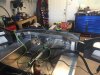
The first thing I did upon arrival was fit the drivetrain. I was lucky enough to borrow a ZF housing in order to facilitate accurate dimensions for my motor placement while I waited for my transaxle to be built. My engine was built by Craft performance and is a 302 bored and stroked to 363, It dynoed right at 500 HP with 460 ft lbs of torque. I utilized a Kennedy Engineering bellhousing to mate the engine and transaxle. I chose to fit the drivetrain with the car mostly together so that after the engine was in place I could take all of the measurements necessary to have GP headers build my bundle of snakes.


Teardown, Priming, and Coating
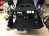
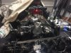
After getting the engine where it needed to be and taking a multitude of measurements for my exhaust builder, I tore down the GT to the bare chassis. Well, not exactly bare, I unbolted the steering rack and left it in place and for some reason which I can't remember I actually left the doors on... Anyways, after it was torn down I cut in the access holes for the fuel tanks and then sanded down the entire chassis in any area that was outside of the cab. After sanding, I primed all of the areas sanded with a self etching primer for maximum adhesion to the raw aluminum surface. Once the priming was complete I coated the whole chassis aside from the cab area in three coats of raptor liner. I did this to lessen the road noise and also I feel that the uniform look of the black gives a nice backdrop to the engine and suspension of this car. If anyone is wondering I used my engine crane to lift the chassis onto some very heavy duty saw horses so that I could lift the car up about 48 inches and get under the car to paint. I would then move the saw horses after the paint or liner had cured and paint the area that was covered by the saw horses.


After getting the engine where it needed to be and taking a multitude of measurements for my exhaust builder, I tore down the GT to the bare chassis. Well, not exactly bare, I unbolted the steering rack and left it in place and for some reason which I can't remember I actually left the doors on... Anyways, after it was torn down I cut in the access holes for the fuel tanks and then sanded down the entire chassis in any area that was outside of the cab. After sanding, I primed all of the areas sanded with a self etching primer for maximum adhesion to the raw aluminum surface. Once the priming was complete I coated the whole chassis aside from the cab area in three coats of raptor liner. I did this to lessen the road noise and also I feel that the uniform look of the black gives a nice backdrop to the engine and suspension of this car. If anyone is wondering I used my engine crane to lift the chassis onto some very heavy duty saw horses so that I could lift the car up about 48 inches and get under the car to paint. I would then move the saw horses after the paint or liner had cured and paint the area that was covered by the saw horses.
Plumbing Brake Lines
After coating the chassis, I installed the brake lines and clutch line. This took some time as I was sent the wrong fittings initially and had to wait on the correct ones to be sent out. Not much to this really, it was a fairly simple process to install the brake lines once I had all of the correct fittings.


After coating the chassis, I installed the brake lines and clutch line. This took some time as I was sent the wrong fittings initially and had to wait on the correct ones to be sent out. Not much to this really, it was a fairly simple process to install the brake lines once I had all of the correct fittings.
Rear Suspension, Brakes and Parking Brake
After the brake lines were run, I reassembled the rear suspension, and mounted the rotors and calipers. I then went through the process of installing the parking brake system onto the car. I followed the directions from the online build manual and got the parking brake system installed without running into too many issues along the way. Drilling and tapping holes into the nice suspension made me pretty nervous, but the directions were straight forward and the process turned out to be easier then I was expecting.


After the brake lines were run, I reassembled the rear suspension, and mounted the rotors and calipers. I then went through the process of installing the parking brake system onto the car. I followed the directions from the online build manual and got the parking brake system installed without running into too many issues along the way. Drilling and tapping holes into the nice suspension made me pretty nervous, but the directions were straight forward and the process turned out to be easier then I was expecting.
Spider, Steering, Evap Fitment, Firewall, and Soundproofing
After assembling the rear suspension and installing the parking brake, I moved onto to getting other things in order. The first thing I did was move the wiper motor position on the spider over to the driver's side in order to make room for the evaporator housing. I measured like for like on both side and simply swapped them around only sectioning out the bare minimum to facilitate the switch. I got them in place and used some epoxy to lock them in where I wanted. After the epoxy was dried I sand through the gel coat and finalized the switch with fiberglass on both sides. I then got a rough fit of the dash into the car with the spider in place in order to locate where the steering shaft would be located, and subsequently installed the bearing that hold the steering shaft where it needed to be and trimmed the dash to accommodate the steering shaft.
I then placed the AC duct work under the dash and trimmed it up to fit so that it would not interfere with the dash. I also made a template of the evap housing ducts so that I could make sure that the plenum would cover the vents that exit the evap housing. Once the dash and plenum were in the right spots, I left the template in place and performed all of the necessary cutting to install the evap housing.
After getting the evap housing cut work done I moved onto the firewall. I utilized a through bulkhead fitting from summit for the AC lines and heater hoses to pass through to the evaporator housing rather then have hoses run through the firewall. After the AC fittings were installed I did the same with the reservoir lines that go to the master cylinders, again I used through bulkhead fittings for this for a cleaner look and hopefully a little more weatherproof. I then installed the reservoirs themselves.
After I had completed all of the above drilling and cutting, I removed everything, cleaned it, sanded it, and applied a combination of eastwood X-mat and dynamat to the entire tub to help with sound and insulation. I had the x-mat left over from my Cobra and it has worked very well at eliminating any heat seepage in the footbox that they are commonly known for.
I'm probably making this all sound a lot simpler then it actually was...
Attachments


Fuel Tanks, Front Suspension, Engine and Accessories
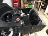
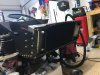
After finishing up the soundproofing I went ahead and put the tanks back in for (hopefully) the final time. Unfortunately, I didn't take any photos of this process but I ended up coming up with my own solution for securing them. First, I installed a piece of aluminum angle at the rear of the tank to brace it in the rear. I wrapped both tanks in a layer of sound deadener and slid them into place. I then got them centered perfectly where the fill hose will attach and measured the remaining gaps on each side. I ordered and installed some high density polyethylene sheets on each side of both tanks to hold them securely centered. Following this I installed another piece of aluminum angle at the front.
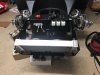
Once the tanks were in place, I reinstalled the front suspension and as I mentioned before I had already dropped the motor back into the car. I have to thank Chris K for the awesome billet transaxle mounts that you can see in the photo below. With the engine in place I installed the AC compressor and alternator along with the water pump and crank pulleys. I know that a lot of people question what brackets will or will not fit and I found a bracket and pulley kit from CVR racing that is specifically for such a tight configuration. After installing all of the accessory drive I ordered approximately 15 belts from Summit, kept the two that fit the best, and returned the rest. Everything lined up very well, and the only thing that I had to rework a little was the spacing for the tensioner on the AC compressor bracket.


After finishing up the soundproofing I went ahead and put the tanks back in for (hopefully) the final time. Unfortunately, I didn't take any photos of this process but I ended up coming up with my own solution for securing them. First, I installed a piece of aluminum angle at the rear of the tank to brace it in the rear. I wrapped both tanks in a layer of sound deadener and slid them into place. I then got them centered perfectly where the fill hose will attach and measured the remaining gaps on each side. I ordered and installed some high density polyethylene sheets on each side of both tanks to hold them securely centered. Following this I installed another piece of aluminum angle at the front.
Once the tanks were in place, I reinstalled the front suspension and as I mentioned before I had already dropped the motor back into the car. I have to thank Chris K for the awesome billet transaxle mounts that you can see in the photo below. With the engine in place I installed the AC compressor and alternator along with the water pump and crank pulleys. I know that a lot of people question what brackets will or will not fit and I found a bracket and pulley kit from CVR racing that is specifically for such a tight configuration. After installing all of the accessory drive I ordered approximately 15 belts from Summit, kept the two that fit the best, and returned the rest. Everything lined up very well, and the only thing that I had to rework a little was the spacing for the tensioner on the AC compressor bracket.
Radiator, Condenser, and Plumbing
Next I went ahead and hung the radiator, this was a straight forward process and I took my time to make sure that it allowed for flex. For the fans I just used the provided push through fan mounts rather then making a shroud. They feel pretty solid and it's something I can always change later. For mounting the condenser I made some brackets out of some aluminum angle and attached them utilizing the radiator mount holes. This gave me a different mount for my condenser rather then mounting directly to the radiator. Just my preference.
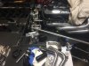
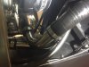
With the engine, radiator, condenser, and evaporator housing in place I was ready to move on to plumbing everything up. Initially I went with silicone hoses from Pegasus racing and utilized their hose joiners to hook everything together. Once all of the coolant plumbing was in, I decided I didn't like the look of all the hose clamps that were required to clamp the hose joiners. I thought long and hard about how I wanted to proceed and eventually merged two ideas together. I ordered some polished stainless 90 degree exhaust bends from Jegs, and also a bead roller. This was my first go at making my own hard lines, but overall there wasn't much to it. I basically used hard 90s to replace most of the silicone 90s I had in place. Luckily Pegasus has an excellent return policy. For the radiator plumbing up front, I did use all silicone and sourced some hose joiners with 5/8 outlets on them for the heater hoses. I also followed all of the advice on the forum and ran a bleeder line from the top of the radiator. (After the AC lines were in place.)
For the AC lines I pretty much just went right with the instructions from vintage air. I mounted the receiver drier forward of the firewall, and I mounted the heater control valve inside of the car. The only time I ran into trouble was when I realized that I would need to essentially build the lines that run through the tunnel to the compressor on the car. I've done a lot of AC work over the years, including building a system for my Cobra, but I've always taken the lines to be crimped. Luckily I looked on Amazon and I was able to obtain a Hydraulic hand held AC crimping tool for around $200 I believe. I got all of the lines roughed up and in place and once I was finished getting the layout how I wanted, I removed hoses, crimped them and installed them back on the vehicle. Looking back I wish I would have just done it myself a long time ago...
Next I went ahead and hung the radiator, this was a straight forward process and I took my time to make sure that it allowed for flex. For the fans I just used the provided push through fan mounts rather then making a shroud. They feel pretty solid and it's something I can always change later. For mounting the condenser I made some brackets out of some aluminum angle and attached them utilizing the radiator mount holes. This gave me a different mount for my condenser rather then mounting directly to the radiator. Just my preference.
With the engine, radiator, condenser, and evaporator housing in place I was ready to move on to plumbing everything up. Initially I went with silicone hoses from Pegasus racing and utilized their hose joiners to hook everything together. Once all of the coolant plumbing was in, I decided I didn't like the look of all the hose clamps that were required to clamp the hose joiners. I thought long and hard about how I wanted to proceed and eventually merged two ideas together. I ordered some polished stainless 90 degree exhaust bends from Jegs, and also a bead roller. This was my first go at making my own hard lines, but overall there wasn't much to it. I basically used hard 90s to replace most of the silicone 90s I had in place. Luckily Pegasus has an excellent return policy. For the radiator plumbing up front, I did use all silicone and sourced some hose joiners with 5/8 outlets on them for the heater hoses. I also followed all of the advice on the forum and ran a bleeder line from the top of the radiator. (After the AC lines were in place.)
For the AC lines I pretty much just went right with the instructions from vintage air. I mounted the receiver drier forward of the firewall, and I mounted the heater control valve inside of the car. The only time I ran into trouble was when I realized that I would need to essentially build the lines that run through the tunnel to the compressor on the car. I've done a lot of AC work over the years, including building a system for my Cobra, but I've always taken the lines to be crimped. Luckily I looked on Amazon and I was able to obtain a Hydraulic hand held AC crimping tool for around $200 I believe. I got all of the lines roughed up and in place and once I was finished getting the layout how I wanted, I removed hoses, crimped them and installed them back on the vehicle. Looking back I wish I would have just done it myself a long time ago...
Attachments


Chris Kouba
Supporter
Excellent work all around Sean. Looks like you're making good progress.
It's a dilemma. I think the price on a Superformance new is around $100K, rolling chassis, no power plant. DIY you will add $30K - $50K to install the power plant and finish the car. An RCR replica is going to cost close to $100K to finish (your labor not included). However, the Superformance (continuation) resale is dramatically higher than the other replicas.As a Superformance owner, I'm really impressed with the skills of Sean and others who build RCR and other cars. This looks like a great build. I wish I had the skills you have, Sean!
I really like RCR's aluminum chassis. It's strong, light, and durable. The suspension is top notch. And, they are in the USA. I'd be interested to know for how much RCR would do a turnkey minus (like Superformance).
I will say that there is nothing like finishing a project like this. The pride of "Built not Bought" has a lot of value. I would put money that Sean will not regret a minute of the build, once he stops itching from the fiberglass!
Jimmy
Fuel System
I haven't really posted any details on how I went about setting up my fuel system. When I was figuring out how I wanted to do it and looking through the forum, I definitely realized that there are a million ways to skin a cat... also realize that the fittings and prep work to do all of this were done before I installed the tanks for the final time. I'm running the Edelbrock Pro-Flo 4 fuel injection system on my car so this required me to have a high pressure fuel sytem, this is how I set it up...
I set the passenger side tank up to be used only as a transfer tank. I mounted a low pressure Holley Mighty Mite fuel pump down low, where the rear suspension runs through. I can turn it off and on via a switch on the dash. I added one return port to the driver's side tank for the transfer line from the passenger side to feed into. For the driver's side I utilized a Carter P4070 rotary vane pump again mounted down low so that it could achieve a good siphon effect from the tank, again activated via a switch on the dash. The carter pumps fuel through the driver side fuel tank access port (bulkhead fitting) and into a Hyperfuel fuel cell. The Hyperfuel unit holds about a half gallon of fuel and has a built in high pressure pump capable of around 90 psi. I was able to squeeze the Hyperfuel unit under the rollbar in a spot that I thought afforded it better protection in case of collision. The fuel cell runs to the fuel rail and fuel pressure is controlled by an Edelbrock fuel rail mounted fuel pressure regulator the system then returns from the regulator to the fuel cell, and there is an additional return from the fuel cell to the driver's side tank. I didn't put any foam or anything into the tanks because I don't plan on racing the car and I didn't want to have to deal with the long term effects later on. I have a 100 micron filter mounted prior to the carter pump and the one on the firewall is a 10 micron filter, that filters the fuel prior to it going to the fuel rail. Also, I originally had a Mighty Mite fuel pump on the driver's side tank as well, but I changed it out for the rotary vane because my wife felt that the Mighty Mite was too noisy... have to keep the boss happy. If anyone would like some additional photos just let me know...
Fast work, well done Sean. I wish I had moved through mine a bit quicker as I love driving it. Could have been driving it years earlier with your pace ")
Spaghetti Time... AKA Wiring
After wrapping up all of the plumbing work it was time to dive in to the most time consuming part of the build thus far, the wiring. I utilized the included harness from Ron Francis (Bare Bonez kit) but I added quite a few relays to the system. I added three fuel pump relays, two fan relays, as well as a relay system for the headlights. I purchase all of my switches from Ron Francis as well going with the Synergy billet style switches throughout. Additionally, I'm running the Digital Guard Dawg keyless ignition on my vehicle.
So, I had to incorporate all of these systems together:
Standard Harness
Edelbrock Pro Flo 4 Harness
Three Fuel Pump Relays
Headlight Relays
Fan Relays
Vintage Air System Wiring
Digital Guard Dawg System Wiring
Additional 6 Circuit Fuse box for Switches
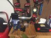
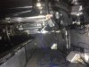
I started by setting the dash in place to determine where I wanted to mount the main fuse box, Digital Guard Dawg box, and additional 6 circuit fuse box. I ended up mounting the main fuse box above the passengers feet and the ignition box and smaller fuse box above the drivers feet. Both are fairly easy to access if necessary. From this point it was just a matter of running the wires where they need to go and incorporating the relays, switches, etc. I worked on this for several weeks for short increments, just tackling one or two things per session until I had wrapped it up. I also built out all of the battery cables at this time and mounted a power distribution block in the area near the battery behind the passenger seat. From the distribution block the fuel pump and other relays draw their power. Each of the fuel pump relays is mounted close to their respective pump so one is behind the passenger seat and the other two relays are behind the drivers seat. The PCM for the Pro Flo Systme is mounted midway down the tunnel behind the passenger seat along with it's relay and fuse. All of the other relays are behind the dash close to the main fuse box. During the time I was working on the wiring the addition of Reincarnation magazine featuring Chuck and Ryan's RCR 40 came out. I noticed they had small fans to the access panels in the engine compartment as a way to circulate air. Since I was in the middle of wiring my car, I quickly ordered the fans an additional relay, and switch and installed them as well.
I have a total of 9 switches on the switch panel and they are in the following order from left to right:
Left Low Pressure Fuel Pump
Engine Compartment Fans
Wiper Switch
Turn Signal
Hazard Lights
Horn
Headlights (w/ high beam built in)
Unassigned / Extra
Right Low Pressure Transfer Pump
I made weather tight connectors for all of the switches so that each switch panel can be quickly and easily removed. Also, I did not like the included Vintage Air controls so I upgraded to their billet version, it matches my switches much better. Initially I thought that I would be able to fit this into the switch panel along side the other switches and this idea failed miserably as their was not enough depth due to the angle the switch panel is mounted at, so I made a nice bracket out of angle aluminum and mounted them centered under the dash.
From looking back at the photos I started this on October 2 and was able to test all of the electrical components on November 29. So it took me about two months of incremental work to complete the electrical system.
"Success is the sum of small efforts, repeated day in and day out." -Robert Collier


After wrapping up all of the plumbing work it was time to dive in to the most time consuming part of the build thus far, the wiring. I utilized the included harness from Ron Francis (Bare Bonez kit) but I added quite a few relays to the system. I added three fuel pump relays, two fan relays, as well as a relay system for the headlights. I purchase all of my switches from Ron Francis as well going with the Synergy billet style switches throughout. Additionally, I'm running the Digital Guard Dawg keyless ignition on my vehicle.
So, I had to incorporate all of these systems together:
Standard Harness
Edelbrock Pro Flo 4 Harness
Three Fuel Pump Relays
Headlight Relays
Fan Relays
Vintage Air System Wiring
Digital Guard Dawg System Wiring
Additional 6 Circuit Fuse box for Switches
I started by setting the dash in place to determine where I wanted to mount the main fuse box, Digital Guard Dawg box, and additional 6 circuit fuse box. I ended up mounting the main fuse box above the passengers feet and the ignition box and smaller fuse box above the drivers feet. Both are fairly easy to access if necessary. From this point it was just a matter of running the wires where they need to go and incorporating the relays, switches, etc. I worked on this for several weeks for short increments, just tackling one or two things per session until I had wrapped it up. I also built out all of the battery cables at this time and mounted a power distribution block in the area near the battery behind the passenger seat. From the distribution block the fuel pump and other relays draw their power. Each of the fuel pump relays is mounted close to their respective pump so one is behind the passenger seat and the other two relays are behind the drivers seat. The PCM for the Pro Flo Systme is mounted midway down the tunnel behind the passenger seat along with it's relay and fuse. All of the other relays are behind the dash close to the main fuse box. During the time I was working on the wiring the addition of Reincarnation magazine featuring Chuck and Ryan's RCR 40 came out. I noticed they had small fans to the access panels in the engine compartment as a way to circulate air. Since I was in the middle of wiring my car, I quickly ordered the fans an additional relay, and switch and installed them as well.
I have a total of 9 switches on the switch panel and they are in the following order from left to right:
Left Low Pressure Fuel Pump
Engine Compartment Fans
Wiper Switch
Turn Signal
Hazard Lights
Horn
Headlights (w/ high beam built in)
Unassigned / Extra
Right Low Pressure Transfer Pump
I made weather tight connectors for all of the switches so that each switch panel can be quickly and easily removed. Also, I did not like the included Vintage Air controls so I upgraded to their billet version, it matches my switches much better. Initially I thought that I would be able to fit this into the switch panel along side the other switches and this idea failed miserably as their was not enough depth due to the angle the switch panel is mounted at, so I made a nice bracket out of angle aluminum and mounted them centered under the dash.
From looking back at the photos I started this on October 2 and was able to test all of the electrical components on November 29. So it took me about two months of incremental work to complete the electrical system.
"Success is the sum of small efforts, repeated day in and day out." -Robert Collier


Similar threads
- Replies
- 8
- Views
- 425
- Replies
- 3
- Views
- 725
- Replies
- 18
- Views
- 1K