Howard Jones
Supporter
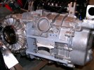
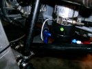
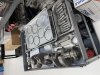
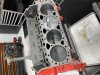
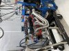
Engine coming together. Short block altogether. There's a lot of work in putting an engine together from selected parts that are not necessarily all from the same vendor. Everything needs to be sized and machined to fit together correctly. But in the end, you have a correctly balanced and properly assembled engine. The AFR heads were pretty close but still got a 2 thou skim to correct the head mating surfaces. My guy said that, again they were pretty close, but we wanted to do a 5-angle job on them and make sure everything was the same cylinder to cylinder. All the valve springs were correct rates and all the valves were the same length. So in short AFR heads were very close out of the box.
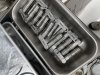
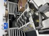
The Callies crank and rods were balanced and the Mahle pistons were together "dead on" the same weight. The rods were balanced end to end which is a process of ballanceing rods that is more complicated than I want to explain here. What was interesting is they were really nearly perfect and required very little modification.
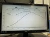
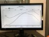
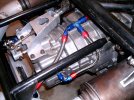
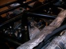
So next is to put the heads on and finish assembling the engine, Then dyno time! Yea!
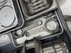
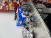
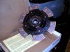
I also called Kennedy Engineering to talk to them about my clutch. I found out I could increase the clamping capacity from what I had now, max torque 530 ft/lbs, to 670 with a change to a 6-puck friction disk. Great! that saves some money. I'll post some pictures of that when it gets here.
The Callies crank and rods were balanced and the Mahle pistons were together "dead on" the same weight. The rods were balanced end to end which is a process of ballanceing rods that is more complicated than I want to explain here. What was interesting is they were really nearly perfect and required very little modification.
So next is to put the heads on and finish assembling the engine, Then dyno time! Yea!
I also called Kennedy Engineering to talk to them about my clutch. I found out I could increase the clamping capacity from what I had now, max torque 530 ft/lbs, to 670 with a change to a 6-puck friction disk. Great! that saves some money. I'll post some pictures of that when it gets here.
Attachments
Last edited:

")