slc Ls 376 and grazziano

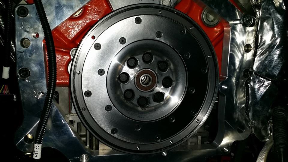
Thought I would share a couple pics that pertain to the adaptation and the application of the Graziano. You may notice that the flywheel has an 8 bolt pattern, and not the typical 6. That is because of the LSX forged crank. If anyone needs this pattern, let me know and I'd be happy to share it. It was a bit rough trying to get it from anyone, so I had to reverse engineer another flywheel I had for the G50. Thankfully it worked.

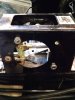
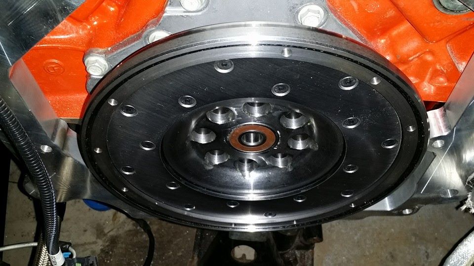
Here is a shot of the flywheel that's been modified to work with the SPEC billet clutch and has been outfitted with a serviceable friction plate so the flywheel never needs to be resurfaced or replaced. The SPEC clutch actually is fully serviceable, so all friction surfaces, intermediate plates and whatnot can be replaced, resulting in an overall savings in exchange for a little more expense up front.

GTM-RCR-Flywheel-Installed.jpg


GTM-RCR-Flywheel-Installed2.jpg


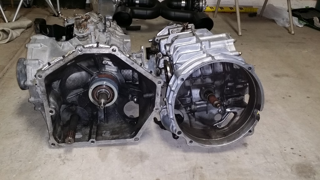
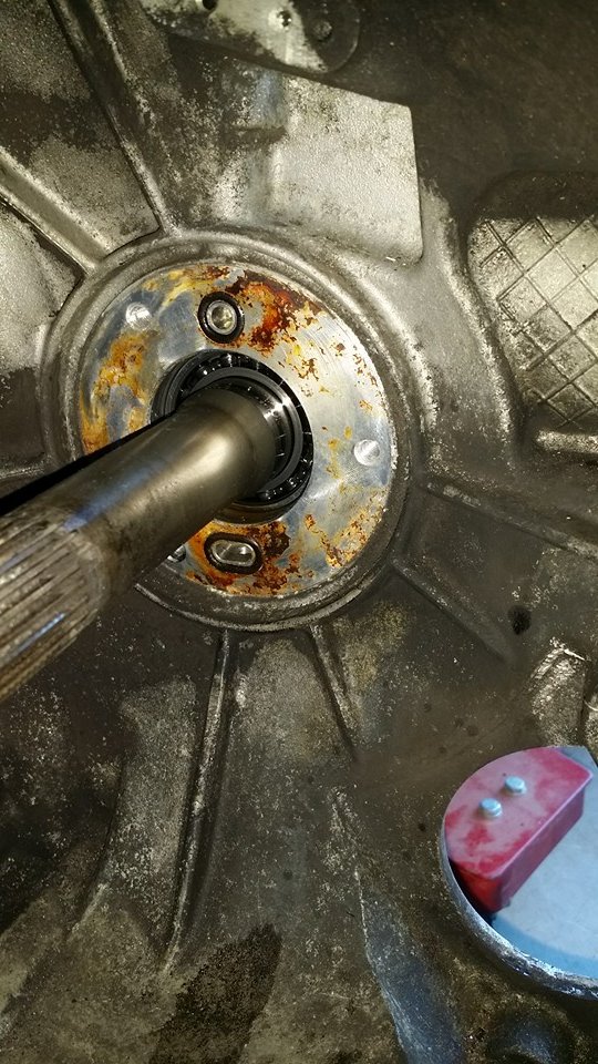
I also changed out the slave cylinder/release bearing from the old revision to the new. I figured that would be a good idea while I had the trans out again and the newer revision is not only better, but substantially cheaper than the original. ($700 instead of $3100)

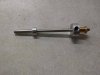
You can see the old one on the left (the large silver ring around the input shaft).

Graziano-vs-Porsche-G50.jpg


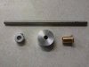
Here it is removed (you can see the inlet and outlet ports with the o-rings, which you should replace while it's apart. My old ones were pretty brittle.

GTM-Graziano-SC-Removed.jpg


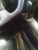
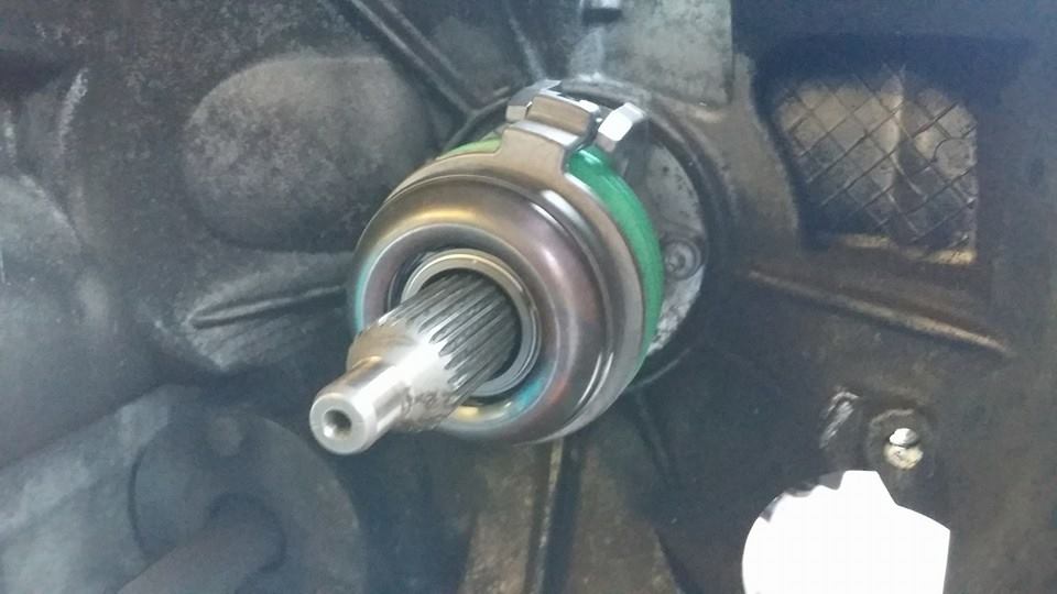
and here is the new one installed:

GTM-Graziano-SlaveCylinder.jpg


The process didn't take very long, but there's not many pictures on the web, even with the Lambo forums as most of them have their mechanic do it, so I thought I'd pass it along. :)
 
Regarding the idea of a shifter guide plate: Looking at the throw on my RCR-supplied shifter assembly, the guide would need to be raised up close to the knob at the top of the shaft to do any good. If the plate were installed near the bottom of the shaft, the lateral movement is less than the diameter of the shaft. There wouldn't be enough lateral movement to get from one slot to another in the guide plate. This would require a pretty high armrest . . .
 
That's why I thought about getting the actual Lamborghini shifter over to Jim Brandwood because if he could get the geometry the same, then the plates, in theory, would work. When I was talking to Jim on the phone, he mentioned that the gate (side to side) could use some adjustment on his shifter, so having the gate may be an option in the future.
 
On another side note. I know there was a discussion regarding the clutch alignment tool. As of yet, I can only find the non-splined tool that Lamborghini uses. I personally would like the splined tool to ensure that everything is lined up. I've checked and ordered the part numbers described in this thread, but none work.

So does anyone else have an idea? I've actually ordered molding equipment to create my own off the input shaft of the transaxle directly. If anyone needs me to make them an extra, I'll post back here when all of my materials arrive. It'll be a thermosetting plastic and not a thermoplastic, but should still do the job instead of hoping to get the friction disks lined up with a non-splined tool. :thumbsup:
 
Coming back to the issue of reverse lockout, centering springs and gated shifters:

This is what I did to avoid accidentally selecting reverse. As a side benefit, it makes it really easy to select 1/2 gear; all you do is push the gear shift all the way to the left and slide it up or down:

The mechanism under the gear shift is such that when you move the shifter to the left, an arm swings to the rear within the mechanism. This makes it possible to install a rod with a large Custom Shaft Collar on it which prevents the arm from swinging back far enough for reverse, but allows it to swing just enough for first or second. When you pull the knob and slide the rod to the left, the Custom Shaft Collar moves clear of the arm and allows reverse to be selected. Push the knob back to the right and the Custom Shaft Collar prevents reverse from being selected, creating a positive reverse lockout.

Here is what I did to install it:
1) Setup the gear shift linkages and adjust everything so that all gears can be selected.
2) Carefully note how far back the lever in the gear shift mechanism moves between selecting reverse vs. selecting 1/2.
3) Drill a 3/16" hole in the side of the gear shift mechanism box. Position the hole to allow for the diameter of the rod to be installed, plus the diameter of the Custom Shaft Collar to be installed. This isn't quite as critical as it sounds, so long as you can turn the Custom Shaft Collar down on a lathe to fine-tune its diameter.
4) Using a long 3/16" drill bit, drill a matching hole directly across the shifter box. The rod will slide in these two holes.
5) Enlarge the hole to 5/16" on the right side of the box only and install a brass bushing to fit, using epoxy blade glue or JB weld or similar. This provides a guide for the sliding rod. The first picture below shows the epoxied bushing in place on the shifter box.
6) With the rod in place, double check the measurements between the rod and the lever on the shifter mechanism to determine the exact diameter of Custom Shaft Collar needed.
7) Machine a Custom Shaft Collar of the correct diameter and thread it for a set screw.
8) Install the fiberglass center console over the shifter box. Using a 3/16 drill bit, push it through the hole drilled in the side of the shifter box and mark where the hole needs to be drilled in the left side of the fiberglass center console for the rod to protrude. Remove the fiberglass center console, drill the hole in the left side only and then replace.
9) Slide the rod through the center console and into the shifter box from the left. Using a long pair of needle nose pliers, slide the Small Standard Shaft Collar onto the rod, then slide the Custom Shaft Collar onto the rod.
10) Using a long allen wrench, tighten the set screws on the rod so that the Custom Shaft Collar will move from behind the lever to clear of the lever, but so that the rod cannot be pulled fully out of the holes. (i.e. the two shaft collars are used to limit the rod travel left and right so that the Custom Shaft Collar can do its job without risking the rod falling out of the hole and bushing on the right side of the shifter box.
11) Install the fiberglass center console over the shifter box. Using a 3/16 drill bit, push it through the hole drilled in the side of the shifter box and mark where the hole needs to be drilled in the side of the fiberglass center console for the rod to protrude. Remove the fiberglass center console, drill the hole and then replace.
12) Install the desired knob on the end of the rod. I designed and 3-D printed a knob to fit. If you like it, you can order your own from Shapeway for about $3.00 plus shipping (see below). If you use this knob, you will also need a small 2-56 screw to hold the knob onto the shaft.

Parts List:
1) 4" Stainless Steel Pin 98404A040 McMaster-Carr
2) Small Standard Shaft Collar 9946K42 McMaster-Carr
3) Bushing (Multi Purpose Flanged Sleeve Bearing) 7815K59 McMaster-Carr
4) Custom Shaft Collar aluminum rod stock 1" diameter https://www.aircraftspruce.com/catalog/mepages/alumround6061t6.php
5) Set Screws 150 Piece Set Screw Assortment
6) Knob end for rod: https://www.shapeways.com/model/upload-and-buy/4866115
7) Little silver sticker to go on the knob: 1 2" Silver Round Vinyl Color Coded Inventory Label Dots Stickers USA Made | eBay
8) 2-56 screw to hold the knob onto the shaft: https://www.radioshack.com/products/2-56-round-head-machine-screws?variant=5717865925

Hopefully this is a little clearer than mud. Here are some pictures to help:
 

Attachments

  • IMG_20160626_081005496.jpg
    IMG_20160626_081005496.jpg
    79.8 KB · Views: 318
  • IMG_20160626_075828540.jpg
    IMG_20160626_075828540.jpg
    146.3 KB · Views: 319
  • IMG_20160626_075945833.jpg
    IMG_20160626_075945833.jpg
    147.6 KB · Views: 284
  • IMG_20160801_114643220.jpg
    IMG_20160801_114643220.jpg
    70.3 KB · Views: 267
  • IMG_20160801_114700293.jpg
    IMG_20160801_114700293.jpg
    57 KB · Views: 290

Michael Fling

Supporter
Coming back to the issue of reverse lockout, centering springs and gated shifters:

This is what I did to avoid accidentally selecting reverse. As a side benefit, it makes it really easy to select 1/2 gear; all you do is push the gear shift all the way to the left and slide it up or down:

The mechanism under the gear shift is such that when you move the shifter to the left, an arm swings to the rear within the mechanism. This makes it possible to install a rod with a large Custom Shaft Collar on it which prevents the arm from swinging back far enough for reverse, but allows it to swing just enough for first or second. When you pull the knob and slide the rod to the left, the Custom Shaft Collar moves clear of the arm and allows reverse to be selected. Push the knob back to the right and the Custom Shaft Collar prevents reverse from being selected, creating a positive reverse lockout.

Here is what I did to install it:
1) Setup the gear shift linkages and adjust everything so that all gears can be selected.
2) Carefully note how far back the lever in the gear shift mechanism moves between selecting reverse vs. selecting 1/2.
3) Drill a 3/16" hole in the side of the gear shift mechanism box. Position the hole to allow for the diameter of the rod to be installed, plus the diameter of the Custom Shaft Collar to be installed. This isn't quite as critical as it sounds, so long as you can turn the Custom Shaft Collar down on a lathe to fine-tune its diameter.
4) Using a long 3/16" drill bit, drill a matching hole directly across the shifter box. The rod will slide in these two holes.
5) Enlarge the hole to 5/16" on the right side of the box only and install a brass bushing to fit, using epoxy blade glue or JB weld or similar. This provides a guide for the sliding rod. The first picture below shows the epoxied bushing in place on the shifter box.
6) With the rod in place, double check the measurements between the rod and the lever on the shifter mechanism to determine the exact diameter of Custom Shaft Collar needed.
7) Machine a Custom Shaft Collar of the correct diameter and thread it for a set screw.
8) Install the fiberglass center console over the shifter box. Using a 3/16 drill bit, push it through the hole drilled in the side of the shifter box and mark where the hole needs to be drilled in the left side of the fiberglass center console for the rod to protrude. Remove the fiberglass center console, drill the hole in the left side only and then replace.
9) Slide the rod through the center console and into the shifter box from the left. Using a long pair of needle nose pliers, slide the Small Standard Shaft Collar onto the rod, then slide the Custom Shaft Collar onto the rod.
10) Using a long allen wrench, tighten the set screws on the rod so that the Custom Shaft Collar will move from behind the lever to clear of the lever, but so that the rod cannot be pulled fully out of the holes. (i.e. the two shaft collars are used to limit the rod travel left and right so that the Custom Shaft Collar can do its job without risking the rod falling out of the hole and bushing on the right side of the shifter box.
11) Install the fiberglass center console over the shifter box. Using a 3/16 drill bit, push it through the hole drilled in the side of the shifter box and mark where the hole needs to be drilled in the side of the fiberglass center console for the rod to protrude. Remove the fiberglass center console, drill the hole and then replace.
12) Install the desired knob on the end of the rod. I designed and 3-D printed a knob to fit. If you like it, you can order your own from Shapeway for about $3.00 plus shipping (see below). If you use this knob, you will also need a small 2-56 screw to hold the knob onto the shaft.

Parts List:
1) 4" Stainless Steel Pin 98404A040 McMaster-Carr
2) Small Standard Shaft Collar 9946K42 McMaster-Carr
3) Bushing (Multi Purpose Flanged Sleeve Bearing) 7815K59 McMaster-Carr
4) Custom Shaft Collar aluminum rod stock 1" diameter https://www.aircraftspruce.com/catalog/mepages/alumround6061t6.php
5) Set Screws 150 Piece Set Screw Assortment
6) Knob end for rod: https://www.shapeways.com/model/upload-and-buy/4866115
7) Little silver sticker to go on the knob: 1 2" Silver Round Vinyl Color Coded Inventory Label Dots Stickers USA Made | eBay
8) 2-56 screw to hold the knob onto the shaft: https://www.radioshack.com/products/2-56-round-head-machine-screws?variant=5717865925

Hopefully this is a little clearer than mud. Here are some pictures to help:

Wonderful Dave! Ty so much for the information.
 
Back
Top