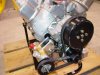
Sandy, your engine looks very nice! I see that you have a special "Boss style" water pump and a serious oil pump support. I don't see your alternator but it is may be installed at the transmission side. Regarding your interesting oil diagram, I have few comments. Be sure that it's not a critic, I don't have any authority to do it. The purpose of this forum is only to exchange different point of view between us
")
.
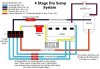
a) Oil tank
Oil tank must be designed with a "deaerator" (not sure about the translation

). Oil return is an air-oil mixture that produce a large amount of foam (emulsion effect). Second oil tank function is to separate oil and air. Obviously, as indicated in the sketch the oil tank should be provided with a large air breather.
b) Oil suction line between oil tank and pump.
This line is critic. Some engines have been destroyded due to a too small suction line (or too long). Gear volumetric pumps have a very large discharge pressure capacity but a very low suction power. When oil is cold, there is a cavitation risk. We have to keep in mind to facilitate oil input to the pump by using large and short hose (12-AN could be OK but 16-AN is better mainly is you use 40W and plus oil viscosity) and to avoid any "U-bend" on the line.
c) Oil radiator
Oil radiator could be necessary (mainly if you want sa save some pounds by using a small oil quantity). However, I prefer install it at the return line side with a 4 ways thermostatic valve (oil too hot is not good but too cold is very bad). At this side, it's the hotest oil point and the oil pressure is very low (to minimise oil leakage risks).
d) Oil filters at the suction side of scavenging stages.
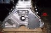
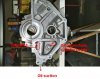
As already explained for the pressure stage, we have to facilitate the oil suction. Oil filters at this place are recommended by the oil pump manufacturer to protect internal parts against foreign particles. However it's preferable to have a large screen at the bottom of the oil sump than individual filters for each stage to facilitate oil suction. About the cylinder head oil return circuit, Ford has provided in the SVO blocks an interesting particle trap design (see picture)
e) Sealled or not sealled engine?
From long time ago, engine builders have observed that crankcase vaccum was the best mean to facilitate crankshaft rotation. With a traditional wet sump, different ways such additional vaccum pump or ejector system connected to the exhaust pipes was used to obtain it. Moreover the free crank and rods rotation, crankcase vaccum design improves the piston ring seal to authorise to use low tension ring in order to save a small amount of internal frictions. One of the dry sump system advantage is to produce a crankcase vaccum. It is the reason that a lot of racing engine are provided with 3, 4 or 5
scavenging stages. These pumps are designed to pull oil mixed with a large air amount. You understand in these conditions that any engine air breather can be acceptable mainly if as the race engines you use low tension rings
.

") . It will save the expensive -16 AN fittings and lines that I have on the valve covers if it does work ok.
. It will save the expensive -16 AN fittings and lines that I have on the valve covers if it does work ok.