
You are using an out of date browser. It may not display this or other websites correctly.
You should upgrade or use an alternative browser.
You should upgrade or use an alternative browser.
Widebody RCR40
- Thread starter Adam H
- Start date
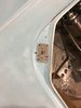
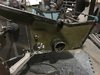
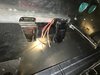
In solving the latch and striker install, I didn't have a lot of confidence the 1/8 thick firewall was going to provide good stability. Others have tied the striker back to the cage. I wanted mine to be removable just in case.

Also, I pulled some flares off the molds I made. I took a stab at blending gulf blue even though it will be painted over.

Also, I pulled some flares off the molds I made. I took a stab at blending gulf blue even though it will be painted over.
OK, new fenders are spliced in. Front of the car looks A LOT more muscular than it previously did. I don't think there is an alternative method to fit the widened gulf wheels with the Goodyear Bluestreak 6.00-15's on the RCR chassis. This fender flare should also accommodate the Hoosier DOT vintage tires in case I have to go that route.


Adam, why did you do the flip?forgot the windshield wiper flip and opening the vent
Windshield wiper arm is supposed to be on the drivers side. Rcr cars come molded for fight hand drive config.Adam, why did you do the flip?
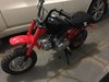
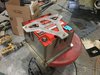
Had some time off for the holidays. With that, I had plans to do considerable work to the 40. What really happened was a Honda mini bike project for my son turned ugly and became a full restoration. After finishing that I bit into the car some.
- Headlight mounting was done with a bonded piece of aluminum. I wanted a single piece to maintain the surface the light would be adjusted from.
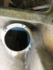
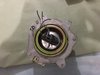
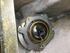
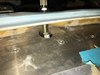
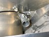
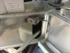
- I wanted something to capture the ends of the coolant tubes. I made a clamp plate from stainless that screws to the tub. I'll do something similar in the back.
- There is an issue when using the quarter turn fasteners on the nostril. As far as I know there aren't dzus fasteners that have grip length long enough to grab the spring mounted under the lip of the clamshell. The fiberglass on the clamshell is pretty thick in some areas. The front edge is 7/16". I made a mount plate to bring the spring up the the same plane as the lip.
- Headlight mounting was done with a bonded piece of aluminum. I wanted a single piece to maintain the surface the light would be adjusted from.
- I wanted something to capture the ends of the coolant tubes. I made a clamp plate from stainless that screws to the tub. I'll do something similar in the back.
- There is an issue when using the quarter turn fasteners on the nostril. As far as I know there aren't dzus fasteners that have grip length long enough to grab the spring mounted under the lip of the clamshell. The fiberglass on the clamshell is pretty thick in some areas. The front edge is 7/16". I made a mount plate to bring the spring up the the same plane as the lip.
Attachments
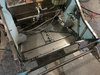
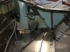
Seat mounting was next on the list. I wanted the rear to fold forward in the event I needed to pull the engine access panel. I added a second cross bar in the cage. This will be used to anchor the shoulder belts. I added some mounting tabs that have rubber bumpers and a feature for some 1/4" Jergens pins. There is a corresponding aluminum brackets on the seat back that are used to affix to the mount brackets.
Attachments
Looks great Adam, you have inspired me to get back on mine. Where did you source your sway bars from? I like the bearing mounts that you have used on the rear.
Thanks
Dennis
Thanks
Dennis
Looks great Adam, you have inspired me to get back on mine. Where did you source your sway bars from? I like the bearing mounts that you have used on the rear.
Thanks
Dennis
The sway bars are standard speedway engineering parts. I wanted to keep them as off the shelf. Calculation for rates was done on an excel doc that I got from this forum somewhere. I think it was from tom’s build. The mounts I sourced from the nascar guys in NC. They were parts I picked up at a swap meet at the speedway there. Many of the parts on my car are sourced used or new from the nascar/circle track/ and road race community. Try to keep the costs in check and I really like the adventure. My basement is filled with stuff.
Some more progress mounting lights. I used the same housings used here http://www.gt40supercharged.com/gt40supercharged.html. It wasn't explained how the housings were mounted to the body. I made some stainless rings that mounted to the housing and used that to tie to some aluminum pieces and 10-32 studs that were bonded to the driving light area of the body.
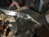
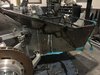
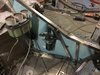
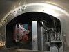
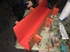
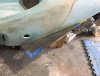
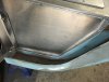
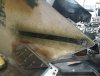
Another thing I wanted to add were closeout panels that better sealed the front subframe to the chassis and lower aluminum plate. I welded a bunch of steel panels in some form of quiltwork to create a mold for them to be made from fiberglass. I still need to fill and smooth the panels but you get the idea.
Another thing I wanted to add were closeout panels that better sealed the front subframe to the chassis and lower aluminum plate. I welded a bunch of steel panels in some form of quiltwork to create a mold for them to be made from fiberglass. I still need to fill and smooth the panels but you get the idea.
Attachments

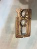
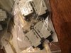
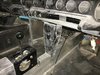
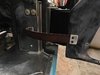
Another thing I wanted to do was wire the car using breakers instead of a fuse box. I picked up some vintage NOS Lockheed Martin breakers made in '59-'60. I'm going to add these to a panel that bridged from where the center console goes under the dash to the bottom of the dash itself.
Attachments
Adam;
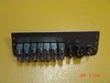
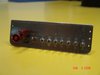
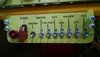
Those are standard aircraft circuit breakers that have been used by the millions. Very reliable units. I had planned on using those same breakers but I stumbled on these combination toggle switch & circuit breakers and decided to use them instead.
Those are standard aircraft circuit breakers that have been used by the millions. Very reliable units. I had planned on using those same breakers but I stumbled on these combination toggle switch & circuit breakers and decided to use them instead.
Attachments
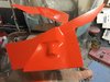
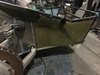
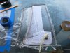
I wanted to add front inner fender liners. Usually these are aluminum and have secondary bolt on bake ducts. I wanted to make all of this as one.
-Make molds from sheetmetal
- Mold the inner panels in fiberglass
- incorporate brake ducts that tie from inner front clamshell to flexible hoses going to spindles
-Make molds from sheetmetal
- Mold the inner panels in fiberglass
- incorporate brake ducts that tie from inner front clamshell to flexible hoses going to spindles
Attachments

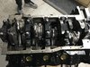
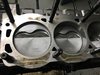
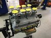
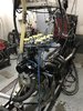
Engine work is under way. I have Hutter Racing Engines in Chardon, Oh working on swapping some parts, installing the 8 stack and getting the engine up and running. I bought the engine built already. Never run, but built. It needed the pistons swapped to high compression from the turbo 9.0:1 CP's that were in there. It's a Dart block 363 with Callies rotating assembly.
Attachments
I'm on the path to wrapping up the mock up phase. I'm a fan of getting as reasonably close to 100% complete before breaking the car down for paint and final assembly.
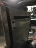
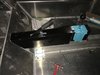
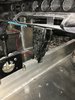
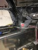
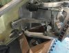
Mounting battery- I made a stainless and aluminum battery box to mount in the passenger footwell. I used an odyssey PC925 battery
Windshield wiper- RCR shipped a wiper motor with a shaft that was too short (1") to reach through the dash pan up through the spider. I had to buy another wiper motor with a 2" shaft.
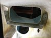
Fresh air vents- I stripped out some Holley throttle bodies from a Chrysler V6 that were 2" diameter and linked them up to some pull cables. They move really smoothly and seal well once closed.
Mounting battery- I made a stainless and aluminum battery box to mount in the passenger footwell. I used an odyssey PC925 battery
Windshield wiper- RCR shipped a wiper motor with a shaft that was too short (1") to reach through the dash pan up through the spider. I had to buy another wiper motor with a 2" shaft.
Fresh air vents- I stripped out some Holley throttle bodies from a Chrysler V6 that were 2" diameter and linked them up to some pull cables. They move really smoothly and seal well once closed.
Attachments
Once again, I'm a big fan of a more complete mock up before starting the final build. So I wanted to finish the interior paneling and will therefore better understand wire routing and the circuit diagrams. I made 2 more molds for a center console over the parking brake and a drop area under the dash for the circuit breakers, passenger fresh air vent control, and maybe the A/C controls.
Also, it's been a long journey but the engine is getting together. Should be in the dyno room in the next few weeks.
Also, it's been a long journey but the engine is getting together. Should be in the dyno room in the next few weeks.
Attachments
Nice.
BTW...I like the drapes.
It makes me happy you noticed those. Things that ugly should never go unnoticed.
LOL!
STOP IT!
'Just blew coffee out my nose!
(Ya...I know...'twas posted years ago - but I just read it and experienced the described result!)
Some updates.
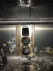
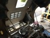
- Got the aircraft breakers and HVAC controls mounted in the panel under the dash. The spacing worked out well and I got 12 circuits, 4 hvac knobs and the fresh air vent pull for the passenger side in there.
- The brake bias control bracket was more work than it looks as that area of the dash is curved and the bracket flat. Needed some fiberglass work and carving to get it all flat.
- Engine is built up and sitting on the dyno. Numbers to follow
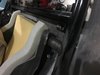
- I wanted some old school looking door checks. There wasn't anything out there that mounted how I prefer or were long enough to allow the door to fully open. I made the keeper plates from stainless and cut up a walmart thick leather belt to make them.
- Got the aircraft breakers and HVAC controls mounted in the panel under the dash. The spacing worked out well and I got 12 circuits, 4 hvac knobs and the fresh air vent pull for the passenger side in there.
- The brake bias control bracket was more work than it looks as that area of the dash is curved and the bracket flat. Needed some fiberglass work and carving to get it all flat.
- Engine is built up and sitting on the dyno. Numbers to follow
- I wanted some old school looking door checks. There wasn't anything out there that mounted how I prefer or were long enough to allow the door to fully open. I made the keeper plates from stainless and cut up a walmart thick leather belt to make them.
Attachments
I've been moving along and getting dangerously close to breaking the car down in preparation for paint and final build. I had an issue at the engine builder with the Dart Pro 225 CNC heads on the engine. There must have been a core shift when they made one (or both) of the heads that when water pressure was put on the heads leaked. The worst leak was a small fountain that was shooting into the #4 exhaust port. They machined through the wall of the casting when the CNC port job was done. Dart offered to pay none, ZERO, of the labor to break the engine back down and rebuild with another set of heads. I thought that an issue like this would be embarrassing enough for them to cover -at least- a good portion. They are holding to their standard warranty claim of parts but no labor or liable costs.
Anyway...
- vacuum bagged some carbon canards. Might paint them body color to look a little more period correct
- Made up some mounts for the front sway bars. Used some 3/8" stainless
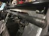
- Wanted to have the rear body prop up and hold in place in a more positive way than a cable. Was thinking a stiff wind could slam it shut and destroy lots of stuff and make me question living any longer. I made some mounts off the sway bar bearings and bonded in aluminum mounts in the body to receive the prop rods
- Made some closeout panels for the rear lower radius rod holes. I think I'll add some kind of boot or brush gasket in the future.
- I didn't like that the ends of the rockers were open. I cut up some leftover glass from the body to close those areas up
- Added a carbon stiffening strip to the inner rear fender area
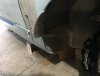
- RCR provided closeout panels for the front of the fuel tanks. I wanted a little more coverage so made another set from .080 aluminum. I also added the front fender winglets like the later Mk1 cars had. I hope it will prevent a little of the road debris from going up the side of the car.
Anyway...
- vacuum bagged some carbon canards. Might paint them body color to look a little more period correct
- Made up some mounts for the front sway bars. Used some 3/8" stainless
- Wanted to have the rear body prop up and hold in place in a more positive way than a cable. Was thinking a stiff wind could slam it shut and destroy lots of stuff and make me question living any longer. I made some mounts off the sway bar bearings and bonded in aluminum mounts in the body to receive the prop rods
- Made some closeout panels for the rear lower radius rod holes. I think I'll add some kind of boot or brush gasket in the future.
- I didn't like that the ends of the rockers were open. I cut up some leftover glass from the body to close those areas up
- Added a carbon stiffening strip to the inner rear fender area
- RCR provided closeout panels for the front of the fuel tanks. I wanted a little more coverage so made another set from .080 aluminum. I also added the front fender winglets like the later Mk1 cars had. I hope it will prevent a little of the road debris from going up the side of the car.
Attachments
Similar threads
- Replies
- 4
- Views
- 916